2874
Eight Channel, Dual-Matrixed, Parallel Transmit RF Power Amplifier for 1.5T MRI1BME, Radiology, Columbia University, New York, NY, United States, 2University of Minnesota, Minneapolis, MN, United States, 3University of Minneosta, Minneapolis, MN, United States, 4Communications Power Corp., Hauppauge, NY, United States
Synopsis
A new, laboratory grade RF power amplifier that offers eight channels of low, CW power for simultaneous transmit and receive applications, and eight channels of high, peak-pulsed power for conventional MRI is presented. These FPGA controlled, multiple transmit channels can be matrix switched into 1, 2, 4, and 8 channel combinations for a range of 2W, 4W, 8W and 16W CW, and 2kW, 4kW, 8kW and 16kW peak power pulses. Further each channel can be used for independent phase, gain, frequency, space and time for maximum flexibility in RF field modulation. This power amplifier meets our wide ranging experimental requirements.
INTRODUCTION
To accompany a head-only, 1.5T experimental system designed for imaging human brain function with minimal mobility restrictions, we needed a new RF power amplifier. To interface an eight channel TEM coil (1) this power amp required eight transmit channels. To make this instrument most versatile and flexible for a wide variety of experimental protocols, the eight channels of this power amp were required to be switched into eight 2kW channels, four 4kW channels, two 8kW channels and one 16kW channel, all wattages reflecting peak powers for conventional pulsed MRI operation. A low peak, 2W mode was also specified, for the same combinations of 8, 4, 2 and 1 channels of 2W, 4W, 8W and 16W, CW output for simultaneous transmit and receive (STAR) operation. (2)METHODS
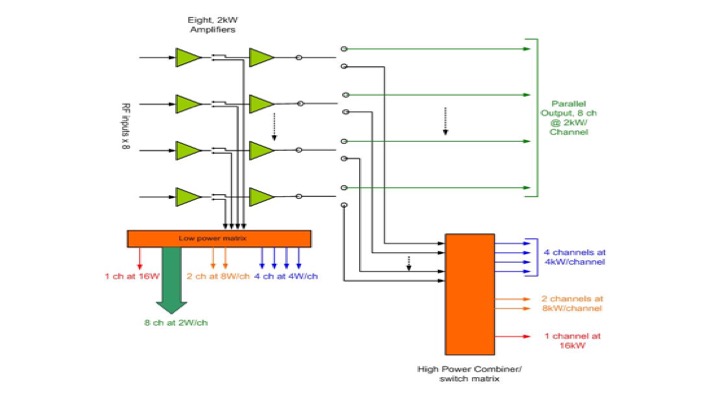
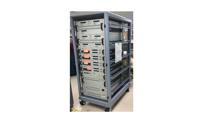
In Figure 1 we see the basic layout of the matix-switched, class AB linear power amplifier. Low gain Ldmos power FETs, rated to 30W but operated at 2W output per stage were used to drive 9th generation 2kW Ldmos FETs for final stage 2kW output per channel. An FPGA controlled PIN switch matrix is used to switch the low power drivers to and from low power output and high power drive. This low-to-high power switch also switched the low channel combinations listed in the introduction. Each low power channel output is monitored by a four port coupler to track RF power output and to trip an overpower failsafe. A similar matrix switch circuit is used on the high power output, to switch the high power channel combinations listed in the introduction. Couplers on each high power output also monitor forward and reverse power to protect the research subject from over-threshold power output and the the power amplifier from excessive reflected power. In Figure 2 we see the full power amplifier cabinet assembled complete with power supplies, power FET boards, matrix switches, combiners, and couplers. The 60" x 24" x 36" deep rack assembly weighs 700 lbs.RESULTS
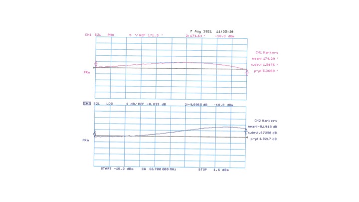
The completed, matrix switched, low power CW, high power pulsed, 1,2,4,8 channel amplifier tests to the following specifications. The amplifier was designed for a frequency bandwidth of 62-66 MHz. Power is16kW /channel (single channel mode), 8kW/channel (dual channel mode), 4kW/channel (quad channel mode), 2kW/channel (8 channel mode). The low power outputs are: 16W/channel (single channel LP mode), 8W/channel (dual channel LP mode), 4W/channel (quad channel LP mode), and 2W channel (8 channel LP mode). The gain measures +72 dB nominal (single channel mode), +69 dB nominal (dual channel mode), +66 dB nominal (quad channel mode), and +63 dB nominal (8 channel mode). The gain flatness is +/- 1db, and the gain stability is +/-0.25db per hour after 15 min soak time. Gain linearity is +/- 1db over 20 dB dynamic range to full mode power. Phase linearity tests to +/- 10 degrees over 20 dB of dynamic range. The pulse tilt is 8 % over 10 msec max. Rise/fall time is less than 500 nsec. The blanking delay is less than 2 usec and the blanked noise power is -154 dBm/Hz. RF sample ports are -69dbc forward / reflected. Mechanicals include BNC(F)x8 input connectors and type N(F)X8 output connectors. RF sample and low power output connectors are SMA (F)x8. A TTL blanking signal is used with TTL active low (RF on=0VDC). As mentioned the cabinet size is 60” high by 24”wide by 36” deep, and weighs 700 lbs. Power source input is 208 VAC single phase. Figure 3 shows test results of the insertion gain (top) and phase (bottom) over a 20 dB dynamic range for a single, high power output channel from 20 to 2000 W.CONCLUSIONS
The goal of designing and building a muti-channel, high-low power, pulsed-CW, experimental power amplifier for the proton frequency at 1.5T has been met. This power amplifier will allow us to perform experiments with multi-channel or single channel, high power pulsed conventional MRI or low-power CW STAR MRI. It will also give multiple, matrix switched combinations of transmit power magnitude, phase, frequency, space and time for almost any imaginable MR experiment. This may well be the most versatile (and complicated) laboratory power amplifier built.Acknowledgements
NIH U01 EB025153-01 "Imaging human brain function with minimal mobility restrictions" M.Garwood, PI, R. DeGraaf, G. Gonzalez, C. Juchem, B. Parkinson, A. Tannus ,T. Vaughan co-PIsReferences
1.) Vaughan JT, Tramm B, Schillak S, Garwood M, Mullen, M, DelaBarre L, Idiyatullin D, Waks M. An RF Coil for a Head-Only MR System. Proceedings 2021 ISMRM, Abstract #0137.
2.) Sohn S-M, Vaughan JT, Lagore RL, Garwood M, Idiyatullin D. In Vivo MR Imaging with Simultaneous RF Transmission and Reception. Magn. Reson. Med. 2016 Dec;76(6):1932-1938
Figures