2813
Safety of 4-channel parallel RF transmission MRI at 3 T: Effects of system uncertainty and system failure pertinent to deep brain stimulation1Physical Sciences, Sunnybrook Research Institute, Toronto, ON, Canada, 2Electrical and Computer Engineering, McMaster University, Hamilton, ON, Canada, 3Medical Biophysics, University of Toronto, Toronto, ON, Canada
Synopsis
Parallel radiofrequency transmission (pTx) technology continues to demonstrate its potential at addressing MRI safety concerns relating to patients with implanted deep brain stimulation devices. One promising technique involves electromagnetic simulation that determine optimized pTx inputs to generate a safe mode of imaging surrounding the implanted device. However, in practice, instrumentation uncertainty can impact the ability of the pTx system to accurately produce the desired signals. The present work studied the safety implications of system uncertainty and system failure in a 4-channel pTx platform. The preliminary results showed that in a worst-case scenario, temperature elevations that exceed MRI guidelines are possible.
Introduction
Deep brain stimulation (DBS) is a highly effective treatment option for patients with certain neurological disorders1. Safe magnetic resonance imaging (MRI) of DBS patients remains a challenge at 3 T because of the increased risks of localized radiofrequency (RF) heating. At present, DBS patient studies involving 3 T MRI have been limited to low RF power pulse sequences that minimize the risks2. However, 3 T MRI is highly desirable without this limitation. Parallel RF transmission (pTx) has recently shown promise in addressing these safety concerns. By utilizing electromagnetic (EM) simulation, an optimized set of RF signals can generate a “safe mode” of imaging surrounding targeted regions that contain conductive impants3. With the limited pTx MRI options available commercially, many researchers have explored custom additions to existing MRI systems to demonstrate the benefits of the technology4. In practice, accurate replication of the optimized RF signals can be challenging, as instrumentation uncertainty can cause signal deviations, and in the worst case, the safe mode could potentially be compromised. This issue requires careful investigation. The present work thus evaluates system uncertainty (RF transmission error) and failure (complete channel loss) effects in a 4-channel pTx platform for 3 T MRI proposed by Yang et al.4, using EM simulations of localized specific absorption rate (SAR) and temperature elevation.Methods
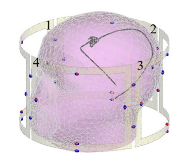
EM simulations were conducted in FEKO (Altair Engineering Inc., Troy, USA) on a homogeneous head model with implanted insulated copper wire and an exposed tip configured in a patient-derived lead trajectory5, as shown in Figure 1. The head model material properties include: an acrylic shell (relative permittivity = 2.5, loss tangent = 0.01), grey matter tissue (conductivity = 0.69, relative permittivity = 67), wire insulation (conductivity = 0, relative permittivity = 2.44) and a perfect copper wire conductor. Thermal simulations were conducted using Penne’s bioheat equation, excluding blood perfusion and metabolic effects6. The 4-channel pTx MRI safe mode parameters used in this work were previously derived according to McElcheran et al.3. These safe mode parameters were then scaled to produce a whole head SAR average of 1.79 W/kg that is within the low-end range for high SAR MRI at 3 T7. Initially, a series of local SAR simulations for a spatial position near the exposed wire tip were executed for pTx system errors in transmitted RF phase and amplitude involving a single channel. The investigation was bounded by the manufacturer datasheet specifications for the actual pTx system hardware4 (phase: ±10º, amplitude: ±0.5 dB). Next, a worst-case scenario optimization was set to determine the maximum local SAR for any pTx system channel error combination in phase and amplitude within a 1 cm cubic volume encompassing the wire tip and its resultant temperature elevation. Last, the effect of pTx system channel failure was studied by powering off each channel independently during safe mode and evaluating the effect on temperature.Results
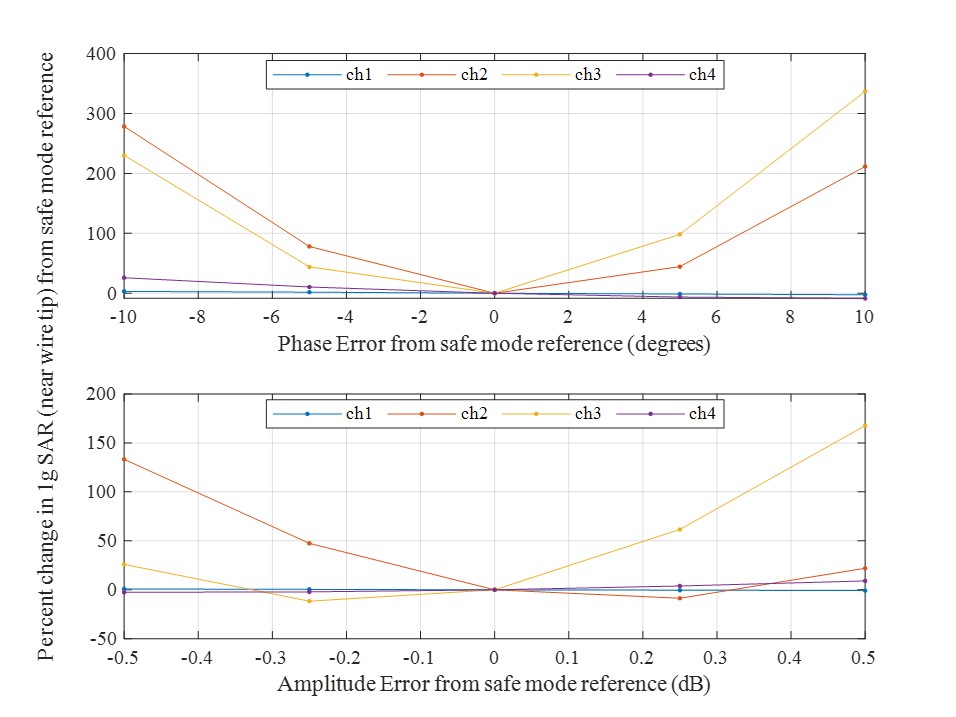
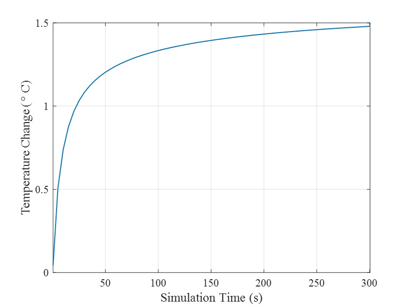
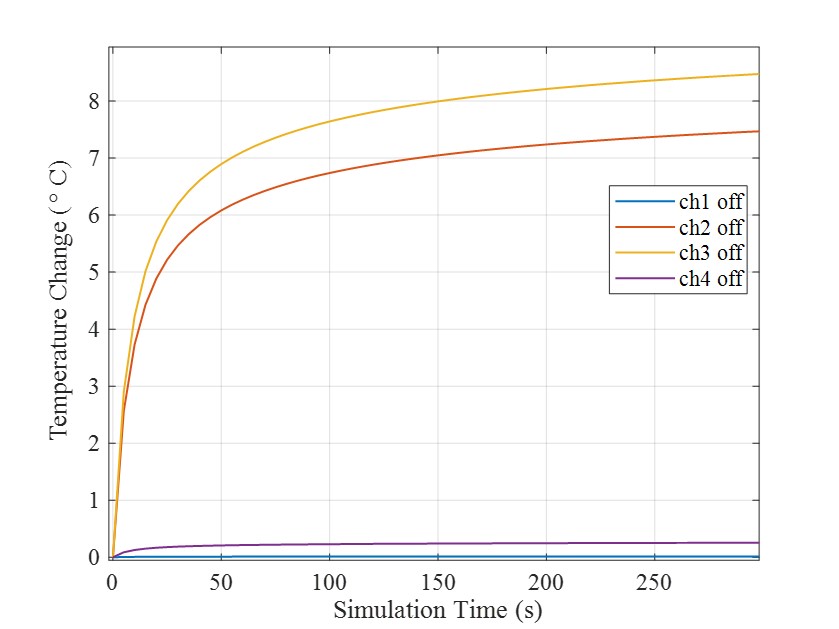
Figure 2 shows the EM simulation result (percent change in local SAR) for errors in phase and amplitude of RF transmission from one channel, with all other channels operating correctly in pTx safe mode. The SAR levels were most sensitive to pTx system errors in channels 2 and 3, with a maximum change (from safe mode baseline SAR) of approximately 300% for both channels. Figure 3 shows the simulated temperature rise for the worst-case pTx system error combination in phase and amplitude. A maximum temperature rise of 1.48⁰C was found, exceeding the current +1.0⁰C safety threshold for MRI at 1.5 T8. Figure 4 shows the simulated temperature change for pTx system channel failure. RF signal failure in pTx system channels 2 and 3 resulted in a maximum temperature rise of approximately 7.5 and 8.5⁰C, respectively, a result that greatly compromised the prescribed safe mode. Consistent with the data shown in Figure 2, failure of channel 2 or 3 produced the worst local SAR increases.Discussion and Conclusion
The simulation showed that temperature elevations were most likely to arise from RF coil elements nearest to the wire tip, as expected, with RF intensity decreasing with distance. In addition, it was evident that two of the four pTx channels made major contributions to pTx MRI safe mode and thus were most sensitive to transmission errors and failure, as shown in Figures 2 and 4. It is well documented that RF shimming capabilities improve with higher system channel count. While two channels were dominant in resolving safety effects and were thus very sensitive to error, the other two channels were important for optimizing B1 homogeneity (data not shown). Last, the simulated temperature results indicated that in a worst-case scenario, system uncertainty and channel failure produced concerning temperature increases that exceed the present guidelines for imaging8. Additional simulations should thus be conducted to investigate the safety impact of different pTx system configurations, including those with higher channel counts.Acknowledgements
No acknowledgement found.References
[1] Fickman, “New Discoveries of Deep Brain Stimulation Put It on Par with Therapeutics.” https://uh.edu/news-events/stories/2021/march-2021/03252021-nuri-ince-deep-brain-stimulation-parkinsons.php. Accessed October 20, 2021.
[2] Davidson et al., “Three-Tesla Magnetic Resonance Imaging of Patients With Deep Brain Stimulators: Results From a Phantom Study and a Pilot Study in Patients.” Neurosurgery 2020.
[3] McElcheran et al., Parallel radiofrequency transmission at 3 Tesla to improve safety in bilateral implanted wires in a heterogeneous model. Magn Reson Med. 2017.
[4] Yang et al., “A Platform for 4-channel Parallel Transmission MRI at 3 T: Demonstration of Reduced Radiofrequency Heating in a Test Object Containing an Implanted Wire.” JMBE 2019.
[5] Wei et al., “Reducing Radiofrequency-induced Heating in Realistic Deep Brain Stimulation Lead Trajectories using Parallel Transmission.” ISMRM 2018
[6] Pennes, “Analysis of tissue and arterial blood temperatures in the resting human forearm.” J Appl Physiol. 1948
[7] Seo et al., “MRI scanner‐independent specific absorption rate measurements using diffusion coefficients.” JACMP 2017.
[8] Medtronic Inc. MRI guidelines for Medtronic deep brain stimulation systems 2015. http://mriquestions.com/uploads/3/4/5/7/34572113/dbs_medtronics_contrib_228155.pdf. Accessed October 20, 2021.
Figures