2775
Virtual Scanner 2.0: enabling the MR digital twin1Biomedical Engineering, Columbia University, New York, NY, United States, 2Columbia Magnetic Resonance Research Center, Columbia University, New York, NY, United States
Synopsis
Virtual Scanner is an open-source MR platform for end-to-end simulation and serves as a digital twin for real MR scanners in hardware and software aspects. In this update, we present new functions including RF pulse design and simulation, hardware-incorporated Bloch simulation that takes into account B0 and B1- fields, and non-Cartesian reconstruction. Three Google Colab notebooks are provided to demonstrate these functions and enable users to perform virtual experiments in a zero-footprint manner. Furthermore, we demonstrate the digital twin concept in a development iteration case using the SPGR sequence.
Introduction
MR scanners have multiple hardware and software layers that require precise coordination to obtain useful images1,2. Open-source sequence development seeks to make waveforms harmonizable across different systems. Virtual Scanner (VS) was developed first to enable virtual scans powered by simulation3,4 for education and research and now as a digital twin of the real scanner. Digital twins of physical systems mirror behavior through simulating the system’s state using real-time data connections5. To approach digital-physical convergence, Virtual Scanner needs to not only simulate any sequence file but also incorporate the main field and coil sensitivity maps (Figure 1). In this update, we also introduce non-cartesian reconstruction demonstrated using radial sequences, simulation with main (B0) and receive field (B1-) maps, and RF pulse simulation. We also demonstrate the digital twin concept with a design iteration using the RF-Spoiled Gradient-Recalled echo (RF-SPGR) sequence.Methods
Virtual Scanner is coded in Python and available on a public open-source repository6. First, simulation and reconstruction of a partially rewound radial UTE sequence using PyPulseq7,8 was shown. Sequence parameters were N = 16, FOV = 250 mm, slice thickness = 5 mm, flip angle = 5 degrees, TR = 10 ms, and TE = 0.38 ms. Non-cartesian reconstruction was accomplished with the conjugate gradient ("cg") method of the PyNUFFT library9.Second, B0 and B1 maps at the same resolution as the phantom can be entered into the simulation function. To demonstrate, hardware maps were acquired on a 3T Siemens Prisma Fit scanner. The B0 map was acquired at isocenter with the ACR phantom and generated using the FSL command line tool10; the B1 map was normalized from a 20-channel complex image data from a standard GRE sequence using a uniform cylindrical water phantom. A single-shot Echo Planar Imaging (EPI) sequence from PyPulseq7,8 was used for the hardware simulations. Before simulation, all maps were down-sampled to the phantom size (32 x 32). Phase unwrapping was performed on the B1 maps to ensure correct interpolation.
Finally, RF pulse simulation and animation scripts were demonstrated in a third Colab notebook. Six pulses were simulated: 90-degree "sinc", "Gauss", and "rect" from PyPulseq, and 90-degree SLR, 180-degree SLR, and Simultaneous Multi-Slice (SMS) translated from the sigpy library11 using a new PyPulseq function12. Spin animations can be generated and downloaded from the notebook.
Digital twin experiment: An RF-spoiled SPGR sequence was tested to demonstrate the digital twin concept (Figure 2). The original sequence tested on the American College of Radiology (ACR) phantom13 did not have ADC phase accommodation. The equivalent sequence at lower resolution was simulated with VS. The sequence was then corrected to align the ADC phase with the changing RF phase. Another simulation validated the correction, and the new sequence was tested on ACR.
Results and discussion
All notebooks can be found online14. Figure 3 shows outputs from the non-cartesian simulation notebook. The geometry is recovered after the radial sampling and reconstruction. This notebook can be modified to simulate other non-cartesian sequences. Hardware simulation outputs (Figure 4) show artifacts caused by the B0 variations (Figure 4(C)) and shading across the B1 Rx channels (Figure 4(E)). Combining the channels using sum-of-squares recovered the image geometry (Figure 4(F)).Figure 5 shows that excitation corresponds to the expected slice locations and thickness. Both modulated PyPulseq pulses showed a dip in Mxy and retained negative Mz components at slice origin. Compared to the PyPulseq "sinc" pulse, the SLR 90 pulse translated from sigpy.rf appeared flatter and with a more linear phase response and less residual Mz. The SLR 180 pulse, however, retained significant transverse magnetization within the slice and failed to invert spins at both edges (Figure 5(E)). The SMS pulse successfully located the three intended slices (Figure 5(F)).
The original SPGR ACR images showed distortion and aliasing in the readout direction (Figure 2(A)). Similar effects were generated by VS (Figure 2(B)) and were corrected by the ADC phase compensation (Figure 2(C)). The final ACR images confirmed this correction (Figure 2(D)). This is an example of a single design iteration where the digital twin helped identify the problem first before acquiring data on the physical twin.
The Colab notebooks are zero-footprint and customizable. However, a full functional User Interface (UI) will make VS 2.0 more accessible for educational purposes. Having a user experience similar to that of a scanner console would also reinforce its role as its digital twin. Real time connection to hardware monitoring is also required to make it a true digital twin5.
Conclusion and future work
In conclusion, this work was a first step in configuring Virtual Scanner as a digital twin of the physical MR scanner. Several new backend functionalities were added to increase the accuracy and versatility of pulse sequence simulations. VS already enables digital twinning of any Pulseq-supported physical scanner at the software level via .seq files. Real-time data connection tying one instance of VS to one physical scanner will be pursued using the MURFI software15, as well as UI updates that allow the user to operate VS in the same way as they operate a real scanner.Acknowledgements
This work was supported by the Seed Grant Program for MR Studies and the Technical Development Grant Program for MR Studies of the Zuckerman Mind Brain Behavior Institute at Columbia University and Columbia MR Research Center site, and was also performed at Zuckerman Mind Brain Behavior Institute MRI Platform, a shared resource, and Columbia MR Research Center site.References
1. Webb AG. Magnetic Resonance Technology: Hardware and System Component Design. Royal Society of Chemistry; 2016.
2. Brown RW, Cheng YCN, Haacke EM, Thompson MR, Venkatesan R. Magnetic Resonance Imaging: Physical Principles and Sequence Design: Second Edition. Vol 9780471720850.; 2014. doi:10.1002/9781118633953
3. Tong G, Geethanath S, Jimeno M, et al. Virtual Scanner: MRI on a Browser. J Open Source Softw. 2019;4(43). doi:10.21105/joss.01637
4. Tong G, Geethanath S, Ravi KS, Jimeno MM, Qian E, Vaughan Jr JT. Virtual Scanner: MRI Experiments in a Browser.
5. Rasheed A, San O, Kvamsdal T. Digital twin: Values, challenges and enablers from a modeling perspective. IEEE Access. 2020;8. doi:10.1109/ACCESS.2020.2970143
6. imr-framework/virtual-scanner: An end-to-end hybrid MR simulator/console. Accessed November 7, 2021. https://github.com/imr-framework/virtual-scanner
7. Ravi KS, Potdar S, Poojar P, et al. Pulseq-Graphical Programming Interface: Open source visual environment for prototyping pulse sequences and integrated magnetic resonance imaging algorithm development. Magn Reson Imaging. 2018;52(February):9-15. doi:10.1016/j.mri.2018.03.008
8. Ravi K, Geethanath S, Vaughan J. PyPulseq: A Python Package for MRI Pulse Sequence Design. J Open Source Softw. 2019;4(42). doi:10.21105/joss.01725
9. Lin JM. Python non-uniform fast fourier transform (PyNUFFT): An accelerated non-cartesian MRI package on a heterogeneous platform (CPU/GPU). J Imaging. 2018;4(3). doi:10.3390/jimaging4030051
10. Jenkinson M, Beckmann CF, Behrens TEJ, Woolrich MW, Smith SM. Review FSL. Neuroimage. 2012;62.
11. Ong F, Lustig M. SigPy: a python package for high performance iterative reconstruction. Proc Int Soc Magn Reson Med Montréal, QC. 2019;4819.
12. Version 2.0 of sigpy2pulseq · imr-framework/pypulseq@5857eca. Accessed November 8, 2021. https://github.com/imr-framework/pypulseq/commit/5857ecaaebbcd7ac4a08dca1dc42ee4e996a04dc
13. ACR AP. Phantom Test Guidance for Use of the Large MRI Phantom for the MRI Accreditation Program. Am Coll Radiol. Published online 2018:1-28.
14. virtual-scanner/virtualscanner/notebooks at master · imr-framework/virtual-scanner. Accessed November 9, 2021. https://github.com/imr-framework/virtual-scanner/tree/master/virtualscanner/notebooks
15. Hinds O, Ghosh S, Thompson TW, et al. Computing moment-to-moment BOLD activation for real-time neurofeedback. Neuroimage. 2011;54(1). doi:10.1016/j.neuroimage.2010.07.060
Figures
Figure 3: Non-cartesian sequence simulation demo. (A) Parameter maps of the numerical phantom; (B) Simulated and reconstructed 2D UTE image (N=16); (C) A screenshot of the Google Colab notebook. All notebooks can be found in the Virtual Scanner repository.
Figure 4: Hardware map simulations using a 32 x 32 single shot EPI sequence. (A) Ideal image generated with uniform maps; (B) B0 map acquired on slice 5 of the ACR phantom at isocenter of a 3T Siemens Prisma Fit scanner; (C) simulated image with B0 map showing intensity artifact; (D) B0 maps of a 20-channel head coil acquired with a uniform cylindrical phantom; (E) 20 channels of B0 map simulation shows shading that correspond with (D); (F) channel-combined image from (E) using sum-of-squares.
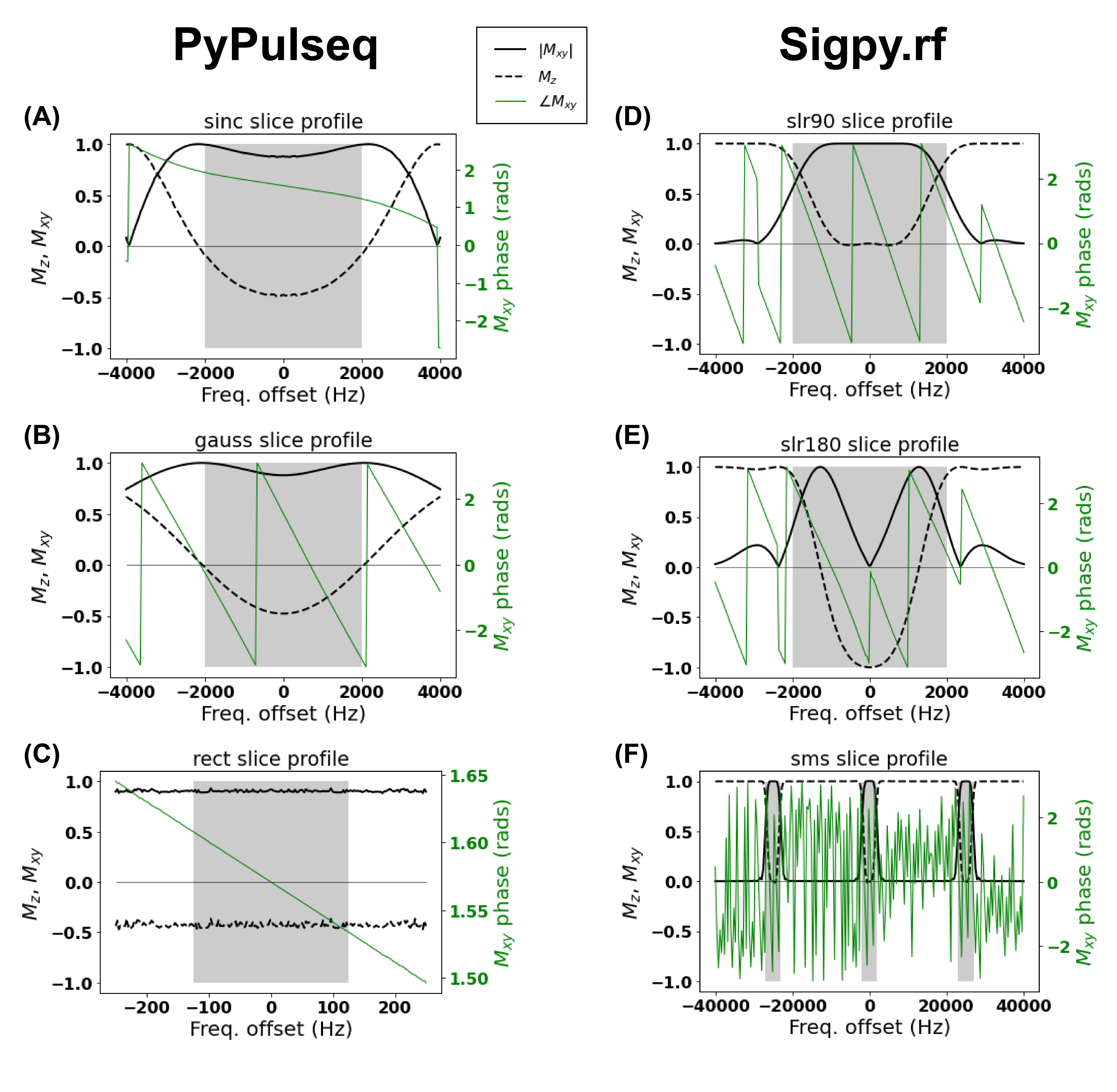
Figure 5: Simulated RF slice profiles. The sigpy pulses were converted to PyPulseq format before simulation11. (A) PyPulseq 90-degree "sinc" pulse; (B) PyPulseq 90-degree "Gauss" pulse; (C) PyPulseq 90-degree "rect" pulse; (D) Sigpy 90-degree SLR pulse; (E) Sigpy 180-degree SLR pulse; (F) Simultaneous multi-slice SLR pulse. Shaded areas indicate slice locations.