2730
A protocol for the acceptance tests of an ultra-high field MR system, in compliance with new standard IEC 62464-1:20181Laboratory of Medical Physics and Magnetic Resonance, IRCCS Stella Maris, Pisa, Italy, 2Imago7 Research Foundation, Pisa, Italy
Synopsis
The European Standard IEC 62464-1:2018 [1] describes the methodologies to carry out acceptance and constancy tests of an MR scanner. Its come into effect extends its applicability in the range of ultra-high field (UHF) tomographers. Here, we present a protocol, with an effective time of acquisition of about 11 hours, developed for the testing of a 7T MR system, in order to address all the requirements of the standard for the evaluation of essential image quality parameters. The protocol provided for the test of two different coil configurations, using proper phantoms.
Introduction
The come into effect of the European Standard IEC 62464-1:2018 replaces its first edition published in 2007, in order to comply with the technological achievements obtained in the last years in the field of MR and to extend its applicability from B0=4T up to 8T, interesting the range of ultra-high field (UHF) tomographers. The standard specifies measurement procedures for the determination of some essential image quality parameters for the quality assessment during acceptance tests of a new MR system. Here we present how the standard was applied in the acceptance tests executed during the testing after the upgrade of a 7T MR scanner to a new platform.Methods
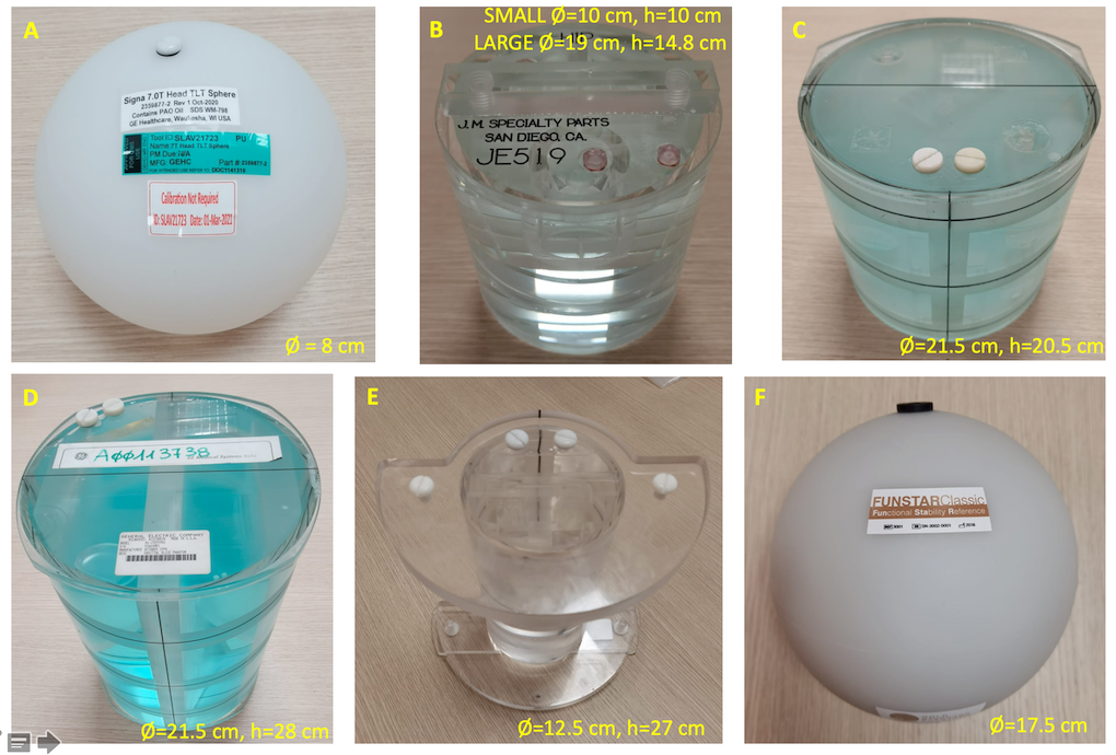
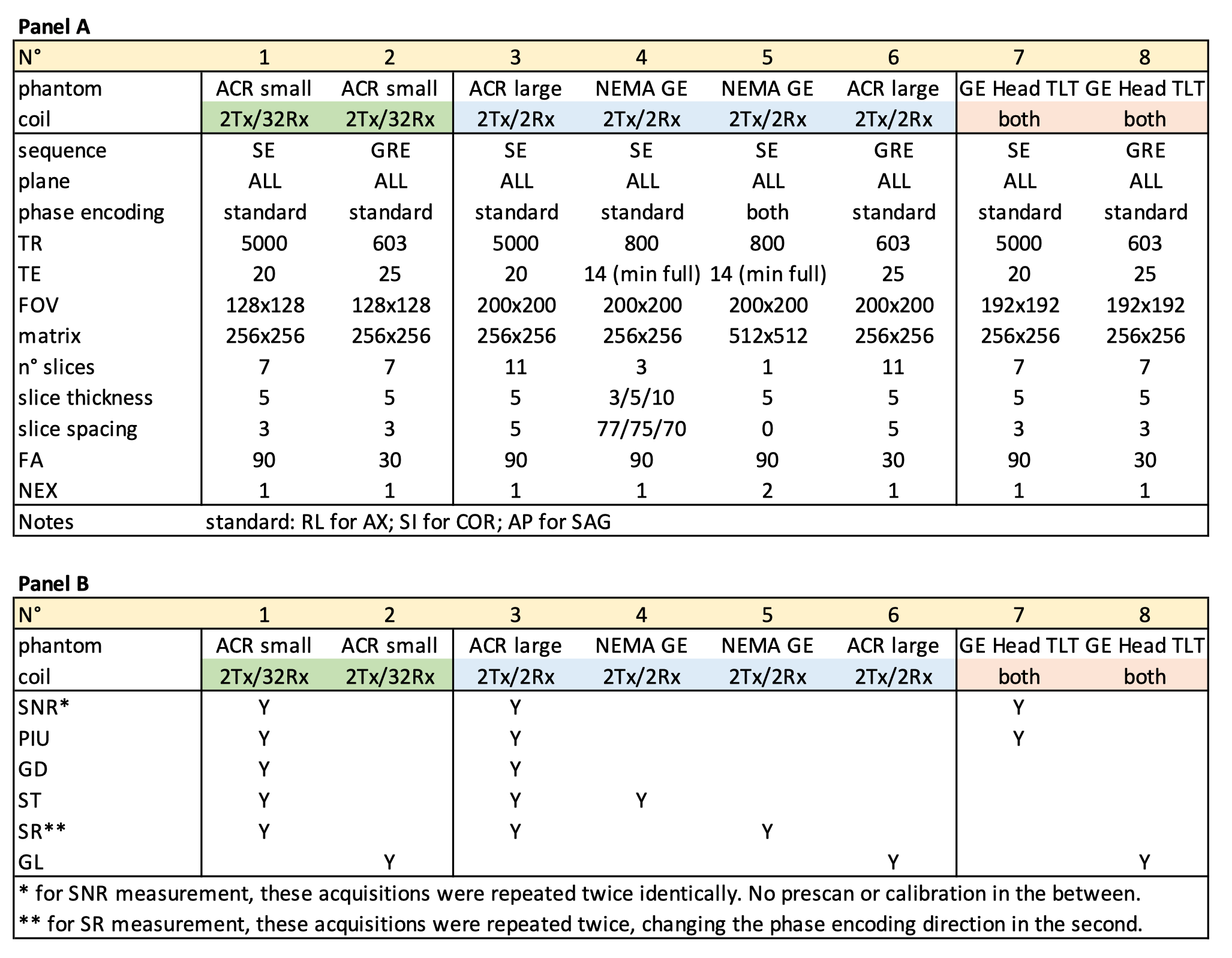
The essential image quality parameters for which the IEC standard defines the measurement methodologies are the Signal-to-Noise Ratio (SNR); the Percent Image Uniformity (PIU), the Slice Thickness (ST); the Geometric Distortion (GD), the Spatial Resolution (SR), and the Ghosting Level, (GL).All the measurements were carried on a 7T MR SIGNA7T (GE Healthcare) system, using two different configurations of the 2Tx/32Rx Nova Medical coil: 1) 2Tx/32Rx as designed and 2) 2Tx/2Rx i.e. using the 2 channels transmission coil also for receiving the signal. Following the standard and based on the parameters to be evaluated, suitable phantoms were used. They differ in terms of structure, shape, and content (Figure 1). The choice of the phantoms was determined by: i) the presence of geometric structures; ii) the dimensions suitable for the used coil (phantom must enter the coil and cover at least 85% of its field of view). Several sequences were executed with different combinations of coil configuration and phantom. Table 1 shows details on different acquisition schemes and indicates which schemes were used to assess each image quality parameter. Considering several repetitions of each for several reasons (acquisition planes, coil-phantom combinations, change of phase encoding direction), a total of 42 acquisitions was performed, for a total effective time of acquisition of about 11 hours.
In Figure 2, the methods (and the formulas) for the measurement of each quality image parameter are reported. For the estimation of ST, the standard’s indications were adapted to the geometric constraints of available phantoms. For ACR phantoms [2-3], the measurement is feasible only on a single slice (thickness 5mm, spacing 3 or 5 mm, for SMALL or LARGE versions respectively), differently from the standard which requires the measurement on 3 slices, with a thickness of 5mm and spacing 10mm. On NEMA GE phantoms, the geometry allows to perform the measurements on 3 slices but 80 mm apart, so the spacing was set to 75mm. For the measurement of GD parameters, the standard provides for the use of a specific cylindric phantom with a series of equally spaced fiducials on the perimeter, to collect N measures for the radius (ri) from which calculate the parameters for GD. To compensate for the absence of a similar phantom, ACR phantoms were used, which contain a grid that can identify reference points to plot the radii (Figure 2). For the measurement of the spatial resolution (SR), the standard requires the use of a phantom provided with a periodic structure with precise ratios between periodicity, distance, and dimensions of the structure. Since such a phantom was not available, the SR was evaluated using the geometric structures present in ACR and NEMA GE phantoms. The firsts contain an internal structure capable of resolving objects and distances equal to 0.9mm, 0.8mm, and 0.7mm (SMALL) or 1.1mm, 1.0mm, and 0.9mm (LARGE). The seconds present 8 comb structures made from small parallel septa, whose thickness is equal to their separation, i.e. the resolution (from 0.5mm to 1.9mm, in steps of 0.2mm).
Results
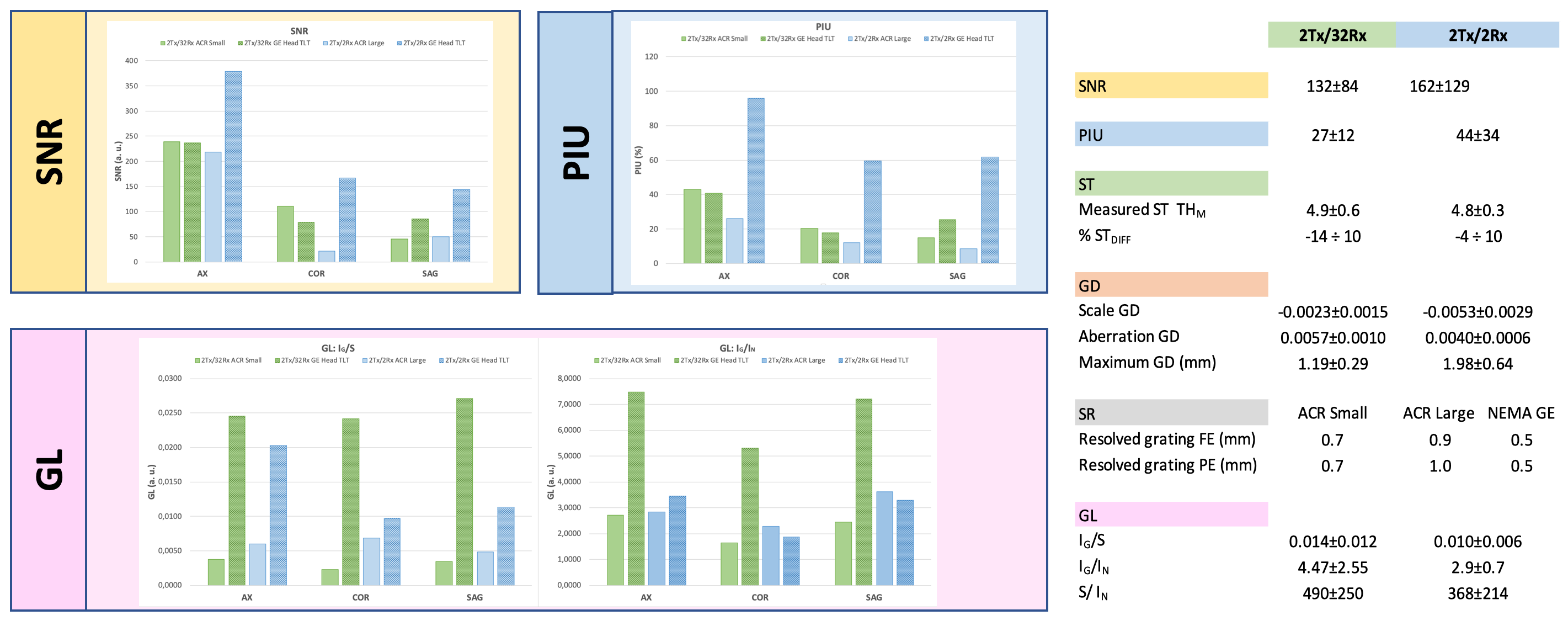
The protocol developed in compliance with IEC 624641:2018 standard was acquired in three consecutive days, providing all the measurements necessary to calculate all the image quality parameters. Numerical results are reported in Figure 3. Best performances of the scanner (higher SNR, higher PIU, lower GL) occur for axial acquisitions in comparison to other planes. ST values are always within the acceptance threshold of 15% of nominal thickness. Maximum geometric distortion is less than 2mm for larger FOVs and about 1 mm for smaller ones. For each test on SR, the maximum resolution was achieved, unless for the measurements obtained in the phase coding direction for the combination 2Tx/2Rx coil-ACR LARGE phantom.Discussion
All the parameters, except SR, were calculated in accordance with the standard, adapting very few details. SR was assessed by adjusting the measure to the geometrical structures of the available phantoms, with very good results. The only parameter with bad values is PIU for which the inherent limitations of UHF compromise the measurement and for which alternative method of calculations should be implemented.Conclusions
This study presents a protocol, developed in compliance with European standard IEC 62464-1:2018, for the evaluation of the image quality parameters during the acceptance tests of a UHF 7T MR system, to characterize the scanner performances.Acknowledgements
This study was supported by the Italian Ministry of Health, under the project “An integrated network for studying developmental brain disorders (DeBrAIn)”, Pediatric IRCCS Network “IDEA”.References
[1] European Standard IEC 62464-1:2018 “Magnetic resonance equipment for medical imaging - Part 1: Determination of essential image quality parameters”. International Electrotechnical Commission, 2018.
[2] Phantom Test Guidance for Use of the Large MRI Phantom for the MRI Accreditation Program, American College of Radiology (ACR), revised 2019.
[3] Phantom Test Guidance for Use of the Small MRI Phantom for the MRI Accreditation Program, American College of Radiology (ACR), revised 2019.
Figures