2729
Comparing geometric accuracy in MRI using a 3D printed distortion phantom1Medical Physics, Clatterbridge Cancer Centre NHS Foundation Trust, Liverpool, United Kingdom
Synopsis
Distortion in MRI can have a significant impact on diagnosis and radiotherapy treatment planning. We have 3D printed a large, low cost phantom that we used along with a CT ground truth to measure 6 MR scanners geometric accuracy. We found significantly more distortion for the 3T and mobile scanners tested which we conclude means they would require a more careful evaluation of distortion if they are to be used for radiotherapy applications and that care should be taken for all scanners where specialist radiotherapy applications such as stereotactic radiosurgery are used.
Introduction
Geometric accuracy is important in MRI if pathology is to be accurately assessed and is critical in radiotherapy planning where distortion in MR images can cause significant deviation from the desired treatment dose1. Geometric distortion is normally assessed by compared the measured distances between a grid of control points with their know distances2. Most current phantoms used for these purposes are either very expensive, bulky, or limited in their coverage. Here we present a simple 3D printed design similar to Jafar et al3 and Wang et al4 that meets all of the requirements of a good distortion phantom and can be produced easily, accurately and cheaply. We also present the results of measurements taken of 6 MR systems from two different manufacturers.Methods
A 3D lattice was designed and 3D printed that consisted of 15 layers of 52 targets 8mm in diameter that where evenly spaced 20mm from one another in every direction. This was then encased in a Perspex cylinder and filled with oil (see Figure 1) to avoid standing wave artefacts at 3T. The phantom was CT scanned at high resolution (0.4x0.4x0.6mm) to act as a ground truth. MR scanning was done with 3D distortion correction enabled.Figure 2 shows the processing used to assess MR distortion. First the phantom was scanned using three sequences (T2 TSE, T1 GRE and T2 SPACE). A 3D normalised cross correlation (NCC) was performed between the MR images and a reference target. The centre of each volume above a set threshold was calculated to identify target positions to sub pixel accuracy. This followed a similar processing method used by Jafar et al3. We then performed a 6-DOF registration to the CT data and recorded the differences between the MR and CT data points to form the distortion grid that could be visualised in 3D or compiled into a metric.
Results
Repeatability measurements showed the error in the mean distortion was ~0.008mm and the maximum (98th percentile) error was ~4%. The results for the 6 scanners varied from an average of 0.33-0.92mm and a maximum (98th percentile) of 0.88mm to 3.14mm (Figure 3). 3T and mobile scanners suffered from up to 3x more distortion than the best 1.5T scanner tested. There was significant variation between all of the 1.5T scanners (excluding the mobile) tested with the worse having almost twice the distortion of the best even though they were all 60cm “wide bore” scanners.Discussion
Jafar et al3 produced a phantom of similar design, and used similar processing to measure mean distortion on a range of scanners. They measured a significantly larger average distortion than we did of between 1.1-1.8mm. This is likely due to the phantoms larger size and increased distortion further from the isocentre and the use of 3D gradient echo sequences which are more susceptible to susceptibility induced distortion.Recent IPEM guidance5 suggests tolerances for distortion for scanners used in radiotherapy planning. They recommend considering two volumes of clinical significance, a 20cm diameter sphere for brains and prostates and a 40cm for full FOV head and neck or pelvis scans. They suggest distortion must be kept <2mm within a volume of clinical significance for standard RT applications and <1mm for specialized RT applications such as SRS.
Using the least distorted T2 SPACE sequence, all but the mobile scanner had <2mm everywhere within the phantom. All scanners except the Skyra 3T achieved <1mm everywhere within 10cm of isocentre but all scanners had areas >1mm beyond 10cm from isocentre. One limitation of this analysis is due to the size and shape of the phantom we cannot assess distortion for all points within the clinically significant volumes.
Conclusion
Static 1.5T scanners are likely to meet distortion requirements for standard RT applications but careful evaluation of distortion is needed if mobile, 3T or specialist RT applications are used.The 3D printed phantom exceeded our expectations in terms of accurate construction and sub millimeter repeatability. FDM 3D printing allowed us to cheaply build a phantom much bigger than is available with resin style printers but is susceptible to subtle warping making a CT Ground truth essential. The nearly spherical control targets at the intersections aided in target detection and no manual intervention was required for any control points. The processing workflow was largely automated producing graphs and contour plots (Figure 3) to help understand how distortion will affect the images produced.
Work has already begun on creating a larger, easier to print phantom that will enable all points within a 40cm volume of clinical significance to be assessed. We also hope in the near future to further assess the impact of shimming, off-isocentre positioning and distortion within more clinically representative cases.
Acknowledgements
No acknowledgement found.References
1. Pappas EP, Alshanqity M, Moutsatsos A, et al. MRI-Related Geometric Distortions in Stereotactic Radiotherapy Treatment Planning: Evaluation and Dosimetric Impact. Technol Cancer Res Treat. 2017;16(6):1120-1129. doi:10.1177/1533034617735454
2. McRobbie DW, Semple S. Quality Control and Artefacts in Magnetic Resonance Imaging. Institute of Physics and Engineering in Medic; 2017.
3. Jafar M, Jafar YM, Dean C, Miquel ME. Assessment of Geometric Distortion in Six Clinical Scanners Using a 3D-Printed Grid Phantom. Journal of Imaging. 2017;3(3):28. doi:10.3390/jimaging3030028
4. Wang D, Doddrell DM, Cowin G. A novel phantom and method for comprehensive 3-dimensional measurement and correction of geometric distortion in magnetic resonance imaging. Magn Reson Imaging. 2004;22(4):529-542. doi:10.1016/j.mri.2004.01.008
5. Speight R, Dubec M, Eccles CL, et al. IPEM topical report: guidance on the use of MRI for external beam radiotherapy treatment planning. Phys Med Biol. 2021. doi:10.1088/1361-6560/abdc30
Figures
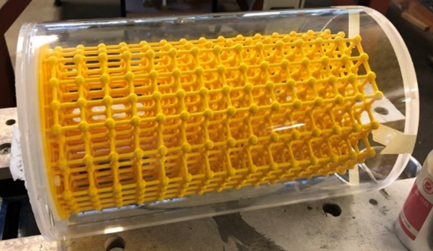
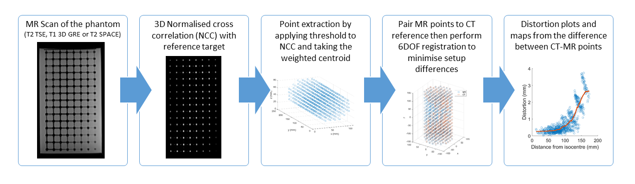
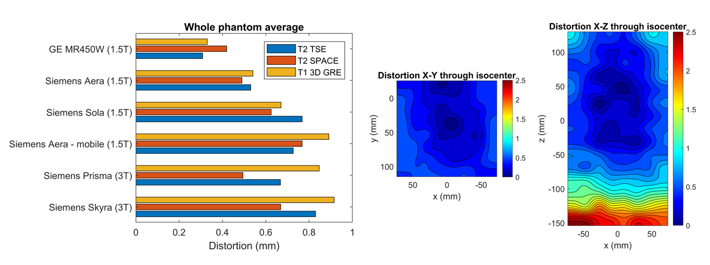
Figure 3: Comparison of distortion between 6 MRI scanners and an example of a distortion map.