2636
MR Safety of Inductively-coupled and Conventional Intra-oral Coils1Dept. of Radiology, Medical Physics, Medical Center – University of Freiburg, Faculty of Medicine, University of Freiburg, Freiburg, Germany, 2Department of Oral and Craniomaxillofacial Surgery, Center for Dental Medicine, University Medical Center Freiburg, Freiburg, Germany
Synopsis
Intraoral coils (IOCs) increase the signal-to-noise ratio in dental MRI exams several times over external coils. However, the intraoral coil placement might be associated with safety hazards such as RF heating. This study evaluates the safety of different IOCs using temperature and E-field measurements to detect temperature hotspots. An inductively-coupled and a wired IOC were constructed, E-field hotspots were detected and the temperature increase was measured showing that it remains below 1K over 6min RF exposure.
Introduction
Dental examinations require soft tissue and hard dental material depiction for an accurate diagnosis. MRI provides an excellent soft tissue contrast, and recent MR studies also showed promising results in imaging of hard tissue. To improve image quality and achievable resolution during dental MRI, intraoral coils (IOCs) were proposed recently1-4, but a detailed safety evaluation of the IOCs has so far not been performed. IOCs are placed inside the oral cavity (e.g. as a dental bite). Similar to active implants or interventional devices, IOCs can induce high electric fields in tissues that come in close contact with the IOC, which poses a potential safety hazard if the temperature rise of 1K is exceeded5. Unlike elongated implant leads and devices, IOCs do not have a single tip or electrodes around which the scattered E-fields cause high local SAR deposition. Thus, it is necessary to investigate the complete coil and find local hotspots. In this study, we propose a test method for safety evaluation of IOCs and provide a safety analysis of an intraoral Tx/Rx loop coil (IOL), and an inductively-coupled flexible coil (IFC) at 1.5T and 3T using E-field and temperature measurements.Materials and Methods
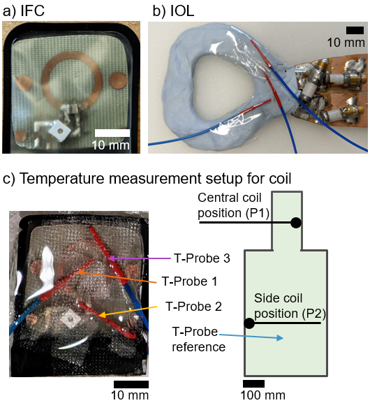
Two IFCs (ø=15mm/30mm @3T/1.5T, width=2mm on 0.3mm-thick PCB) were constructed and inductively coupled to external Rx coils of the MR systems. MR images were acquired at a clinical 3T (PrismaFit, Siemens) and 1.5T (Aera, Siemens) systems with T2-SPACE sequence (see4). IFCs were covered in a dental x-ray film (Fig.1a). In addition, an IOL was built by cutting out a loop (dental bite form) from a 1mm-thick copper plate, which was isolated using dental resin and water-tight disposable plastic (Fig.1b)2. To assess coil safety, a workflow was defined starting with an electric (E) field mapping using an electro-optic E-field sensor (EOS)6-7. The IFCs were positioned in a water bath (13x13cm²), and an excitor loop coil was placed in parallel (distance=20mm) outside the the bath . E-field maps were acquired on a planar grid 1mm above the IFC surface with 1x1mm² resolution for tuned and detuned IFC. E-field measurements were also performed with the IOL, which was also the excitor. In the E-field maps the location of the maximum (hotspot) was determined. Afterwards, temperature measurements were performed with 3 fiber-optic temperature probes (FOTEMP6-19; Optocon AG, Dresden, Germany) that were placed on the hotspots (Fig.1b). During the measurement the coils were placed in an ASTM phantom filled with 30L of HEC-gel (31g/L hydroyethylcellulose, 1.55g/L NaCl) at two different positions P1 or P2 (Fig.1c). First, the IFCs were measured with cross-diodes for passive detuning. Then, the crossed-diodes were removed to simulate resonant coil coupling with the body coil as a potential component failure. For RF heating a SPACE sequence (whole body SAR of 0.6W/kg) and an RF-only sequence (maximum RF power deposition of 4W/kg) were applied over a duration of 360s. Measurements were repeated with the IOL where the RF power was directly applied to the coil via an RF signal generator and power amplifier (3.2W and 100% duty cycle).Results
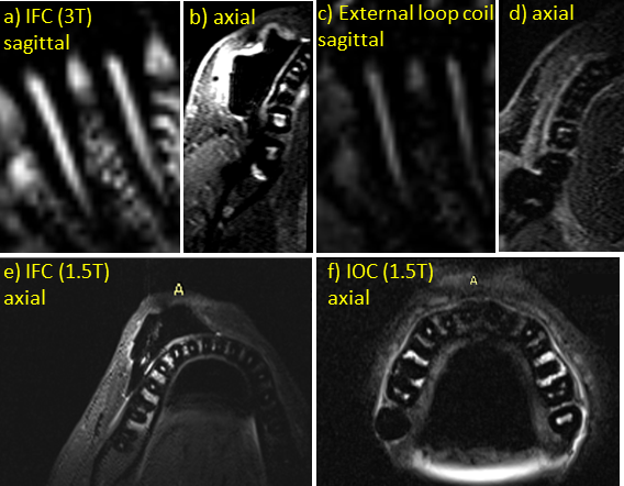
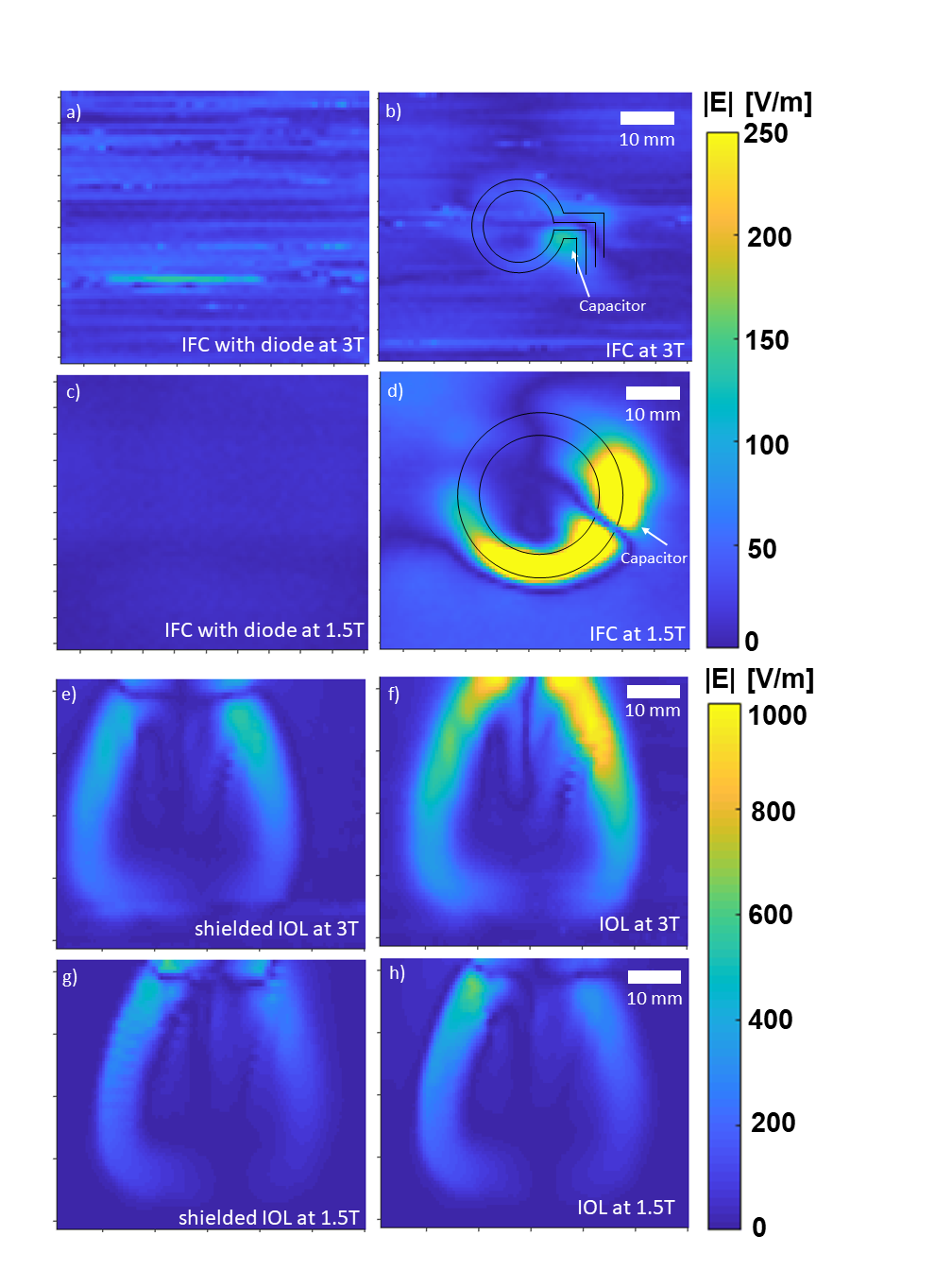
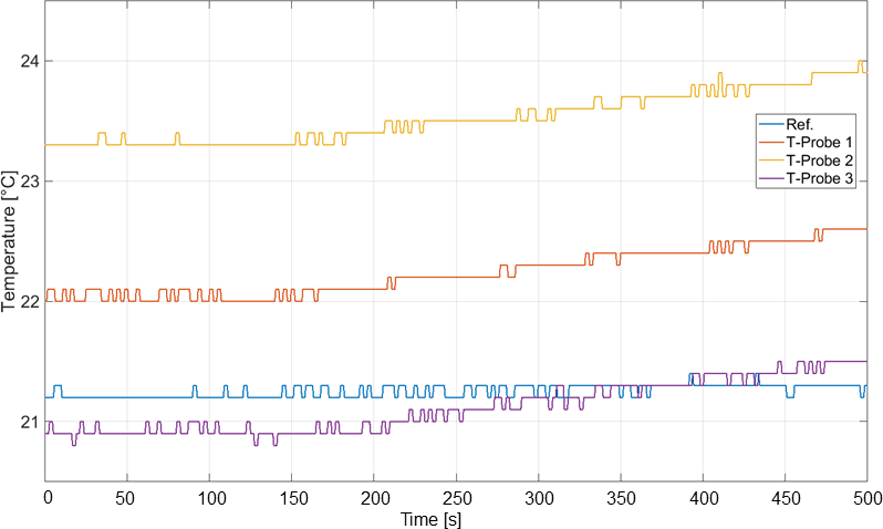
In-vivo measurements of IFC (3T) provide an SNR=91 compared to an external loop giving an SNR=15 yielding an SNR gain of 6 (Fig.2a-d). The MR images of the 1.5T acquisition also show a 3-fold signal enhancement around the coil in Figs.2e,f respectively. In Fig.3, the E-field map of the IFC with a crossed diode shows no detectable increase of the E-field whereas the IFC without diodes (Fig.3b) has a distinct local hotspot around the coil capacitor used for tuning. The same behavior was observed at 1.5T (64MHz) with increased intensity. The IOL shows the highest E-field at the feed port in Fig.3f. (Fig.3e). At 1.5T, a 40% reduction in the peak E field value was observed compared to 3T. The temperature measurements show no heating during low-power deposition with the SPACE sequence, but the maximum-SAR protocol resulted in a detectable temperature increase of 0.6K for the side position P2 (Fig.4). Without diodes a temperature increase of 0.3K was detectable at P1. IOL data resulted in a max. temperature increase of 0.3K (shielded) and 0.5K (unshielded). All temperature increase values are listed in Table 1.Discussion
The hotspot location of the EOS is in agreement with the measured temperature results, giving a maximum temperature increase around the capacitors. Overall, the MR safety standard specified in the International Electrotechnical Commission (IEC 60601-2-33) that evaluates temperature rise after 6 minutes to be below 1K is fulfilled for this specific coil case. Current ASTM safety standards do not explicitly mention intra-oral coils, but guidelines for active implanted devices are applicable as a reference8. IOL E-field maps were consistent with previous simulation studies showing that E-fields are concentrated around the feed port. This can be prevented by feeding the IOL using a shielded and balanced port, i.e., a dual strip-line. A simple shielding of the feedport already reduces the peak E-field by 50% (Fig.3e-f).Conclusion
Dental MRI with IOCs provides a clear SNR gain and can be performed without apparent RF safety hazard when the patient is in a typical central position. Even if safety components such as crossed diodes fail, patient safety can be guaranteed for the tested coil setup.Acknowledgements
No acknowledgement found.References
1. Ludwig U, et al. "Dental MRI using wireless intraoral coils." Scientific reports 6.1 (2016): 1-11.
2. Ozen AC, et al. "Design of an Intraoral Dipole Antenna for Dental Applications." IEEE Transactions on Biomedical Engineering (2021).
3. Idiyatullin D et al. Intraoral approach for imaging teeth using the transverse B1 field components of an occlusally oriented loop coil. Magn Reson Med. 2014;72:160–165.
4. Tesfai AS, et al. "Inductively Coupled Intraoral Flexible Coil for Increased Visibility of Dental Root Canals in Magnetic Resonance Imaging." Investigative Radiology (2021).
5. International Electrotechnical Commission (IEC). Medical electrical equipment: particular requirements for the safety of magnetic resonance equipment for medical diagnosis. Int Stand IEC 60601-2-33. 2002.
6. Reiss S et al. An optical setup for electric field measurements in MRI with high spatial resolution. Phys Med Biol. 2015 Jun 7;60(11):4355-70. Epub 2015.
7. Lottner T et al. "A Transfer Function Measurement Setup With an Electro-Optic Sensor for MR Safety Assessment in Cascaded Media," in IEEE Transactions on Electromagnetic Compatibility, vol. 63, no. 3, pp. 662-672 2021.
8. Technical Committee ISO/TC 150. ISO/TS 10974. Assessment of the safety of magnetic resonance imaging for patients with an active implantable medical device. Geneva Switz Int Organ Stand. 2012.
Figures