2635
Dependence of Electromagnetic Exposure on Design and Excitation Positions of 3T Two-Channel Whole-Body Birdcage Coils1Max Planck Institute for Human Cognitive and Brain Sciences, Leipzig, Germany, 2U.S. FDA, CDRH, Office of Science and Engineering Laboratories, Division of Biomedical Physics, Silver Spring, MD, United States, 3EMConsulting, Zurich, Switzerland
Synopsis
The safety assessment of RF exposure in MRI heavily relies on electromagnetic simulations. As there are numerous different coil designs on the market, this assessment is typically performed with sets of generic coil geometries to cover the commercially available bore diameter and coil lengths. This abstract investigated the effect of other design parameters, which are currently less considered. Our results show that feed-port positioning and non-ideal tuning of the coil may considerably alter the RF absorption pattern in an oval phantom, and even more so the E-field distribution outside the phantom.
Introduction
3T whole-body birdcage coils are designed to generate a homogeneous B1+ field while simultaneously maintaining the RF safety limits inside the patient. The electric (E) field inside the patient is difficult to assess but is not a limiting factor for volume transmit coils. SAR averaged over the mass of the body or specific body parts and over a specified time is the primary RF safety limit for these scanners1. MR examinations are increasingly being performed on patients with medical devices. Full 3D-EM simulations are used for the evaluation of RF safety limits. Usual domain decomposition consists of separating the human EM exposure, due to the MR RF transmit coil, from the assessment of the medical device RF response. The former could be accomplished by collecting EM field exposure data obtained in multiple anatomically correct patient models at different landmark positions and in a variety of MR whole-body birdcage coils2. Based on the limited availability of MR coil design data, generic coil models are typically developed to evaluate EM field exposure in human models. Attempts to validate E-field exposure of commercial whole-body birdcage coils using a generic coil model had limited success3,4. The commercial library MRIxViP3.0T5 (IT’IS Foundation, Zurich, Switzerland) provides EM exposure distributions inside human body models. However, MRIxViP3.0T provides limited validation information that the library data covers EM exposure distribution cases occurring in commercial MR scanners, including scanners with two-channel parallel transmission.Methods
“Generic” and “vendor-specific” coil models were constructed using the same coil geometry but with different azimuthal placement of the excitation ports: (i) 270/0 degrees, (ii) 135/225 degrees, and (iii) as in Siemens commercial coils (exact location cannot be disclosed). Two widely used whole-body birdcage coils from the MAGNETOM Verio (70cm bore) and MAGNETOM (60cm bore) systems (Siemens Healthcare GmbH, Erlangen, Germany) were selected for this investigation. The full information of simulation workflow for “vendor-specific” and “generic” coil models are presented in6. Four “generic” coil models were built using the geometry of MRIxViP3.0T coils B75_L40, B75_L50, B65_L40, B65_L50 described in7. Quadrature excitation was applied. “Generic” coils were also excited at all 32 ports (so-called G32 design) as in8. As a proof of concept, the results for an oval phantom were obtained based on a co-simulation approach9.Results and Discussion
The qualitative comparison of different MR scanner and RF safety related quantities revealed that: (i) B1+ profiles (Figs. 2 and 4) were very similar for most investigated cases except in the case of the Siemens “realistically tuned” coil, i.e., the coil with minor deviation from the ideal S parameters. Unexpectedly, this case results in the best B1+ homogeneity over the center axis slice. (ii) SAR and Erms profiles (Figs. 2-5) were very similar for most cases except Siemens “vendor-specific” coil models. The largest discrepancy relative to the “average” SAR profile was observed for the Siemens “realistically tuned” coil. (iii) Erms profile in air and in the oval phantom for XZ plane, 75mm below the iso-center, which is substantially different between the “vendor-specific” and the “generic” coil models. Changing the “generic” coil length did not make this Erms profile to become more similar to the “vendor-specific” profile in air. A mismatch up to 20dB was observed at some positions in close proximity to phantom external face.For the coils with 70cm bores, the negligible difference in SAR profiles can be explained by very similar current distribution in the rings and rungs. For coils with 60cm bores, the coil load without cylindrical symmetry is the reason for the variation of the coil current distributions. For the G32 design, the distribution of the current amplitudes in the rungs was still close to the “ideal” case, whereas other coil designs exhibited larger deviations. Even more substantial variation, i.e. a mismatch up to 5dB at some location inside the phantom, was observed for “vendor-specific” port locations, especially for the 60cm bore coil. In all cases, the variation increased if Siemens Trueform mode was applied, i.e., the excitation with the same amplitude, but the phase other than 90 degrees10.
A major goal of MR scanners is to generate the most suitable B1+ profile in a patient while keeping acceptable levels of SAR (head, whole body, partial body; depending on the patient’s land mark position). The spatial distribution of the E-field inside or outside the patient’s body for volume transmit coils is not regulated by IEC 60601-2-33 or any other RF safety related standard. This E-field distribution, however, is of great importance for the safety assessment of medical devices.
A quantitative comparison of coil design consequences for given AIMDs, passive implants, etc. requires simulation of a set of “vendor-specific” coil models with human models, preferable as in MRIxViP3.0T. This is a large task which may require collaborative projects, especially when also including RF shimming, i.e., excitation of the RF coil ports with different amplitude and phases
Conclusion
Our investigation provided evidence that (i) quadrature excitation in “vendor-specific” coil models generate EM field profiles substantially different to “generic” coil models, especially in case of “realistically tuned” coils, (ii) the location of the excitation ports impacts the prediction of EM field profiles, especially for non-quadrature excitation mode.Acknowledgements
DISCLAIMER: The mention of commercial products, their sources, or their use in connection with material reported herein is not to be construed as either an actual or suggested endorsement of such products by the Department of Health and Human Services.References
[1] Medical Electrical Equipment-Part 2–33: Particular Requirements for the Basic Safety and Essential Performance of Magnetic Resonance Equipment for Medical Diagnosis. International Electrotechnical Commission Standard 60601-2-33 Ed. 3, Geneva, Switzerland, 2010.
[2] Technical specification ISO/TS 10974:2018, “Assessment of the safety of magnetic resonance imaging for patients with an active implantable medical device,” The International Organization for Standardization, 2018.
[3] E. Lucano, M. Liberti, T. Lloyd, F. Apollonio, S. Wedan, W. Kainz, and L. M. Angelone, “A numerical investigation on the effect of RF coil feed variability on global and local electromagnetic field exposure in human body models at 64 MHz,” Magn. Reson. Med., vol. 79, no 2, pp. 1135-1144, 2018.
[4] M. Murbach, et al., “Thermal tissue damage model analyzed for different whole-body SAR and scan durations for standard MR body coils,” Magn. Reson. Med., vol. 71, pp. 421-431, 2014.
[5] https://itis.swiss/virtual-population/explib/mrixvip3-0t
[6] M. Kozlov, et al., “Modeling electromagnetic exposure in humans inside a whole-body birdcage coil excited by a two-channel parallel transmitter operated at 123 MHz”. IEEE Journal of Electromagnetics, RF and Microwaves in Medicine and Biology (4), pp. 247 – 253. (2020).
[7] A. Yao, et al., “Induced radiofrequency fields in patients undergoing MR examinations: Insights for risk assessment”. Physics in Medicine and Biology, 66 (18), art. no. 185014, (2021).
[8] Meiqi Xia1, et al., “Effects of patient orientations, landmark positions, and device positions on the MRI RF-induced heating for modular external fixation devices”. Magn Reson Med. 2021;85:1669–1680.
[9] Kozlov M. and Turner R., “Fast MRI coil analysis based on 3-D electromagnetic and RF circuit co-simulation,” J. Magn. Reson., vol. 200, pp. 147–152, 2009.
[10] I. Panagiotelis and M. Blasche, “TrueForm™ technology,” MAGNETOM Flash, vol. 40, pp.114-119, 2009.
Figures
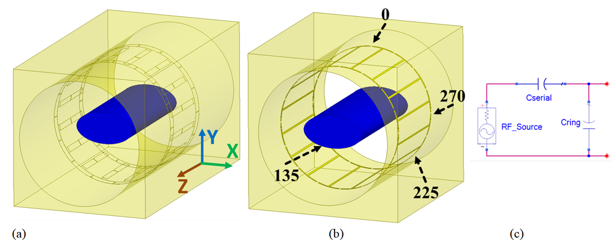
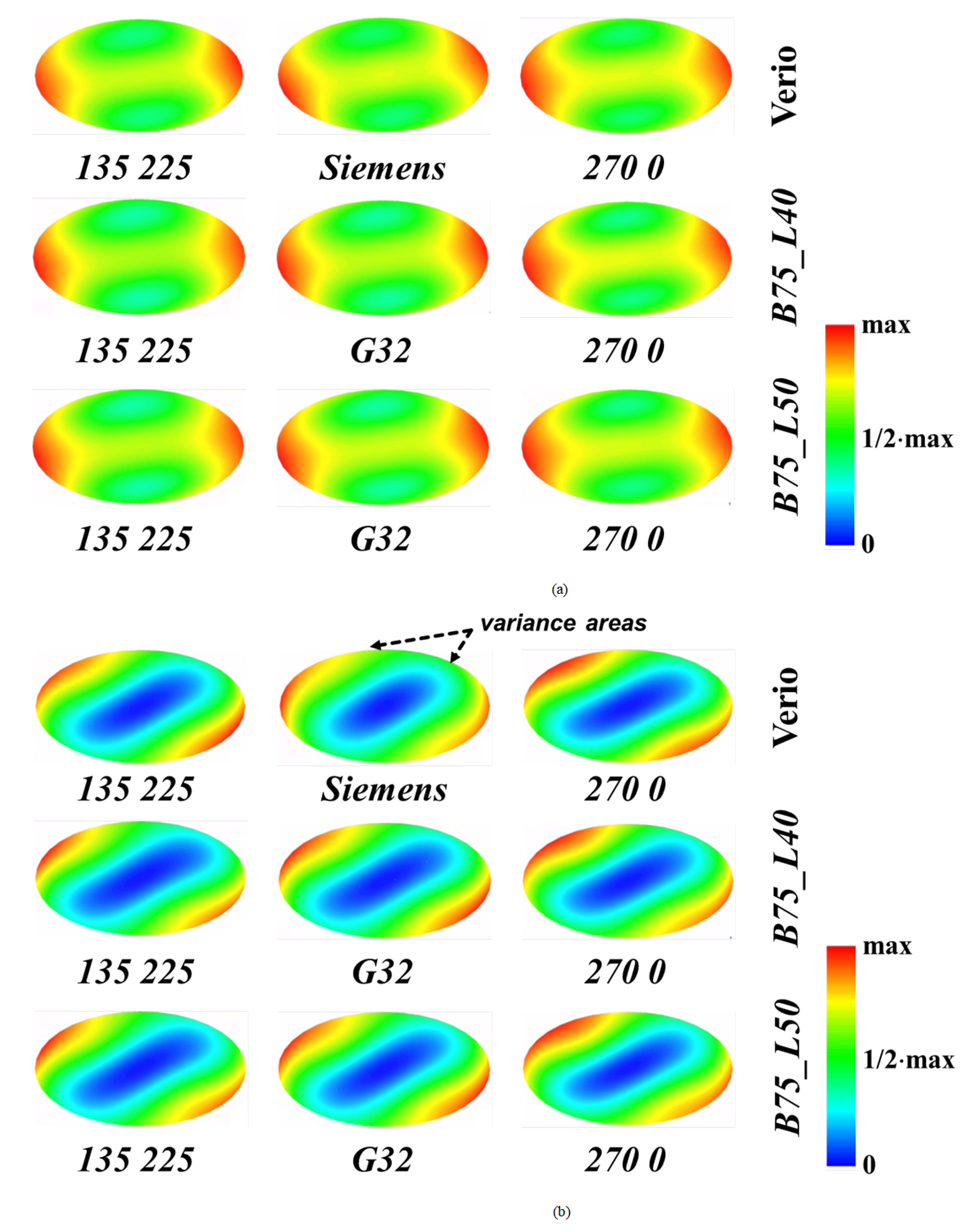
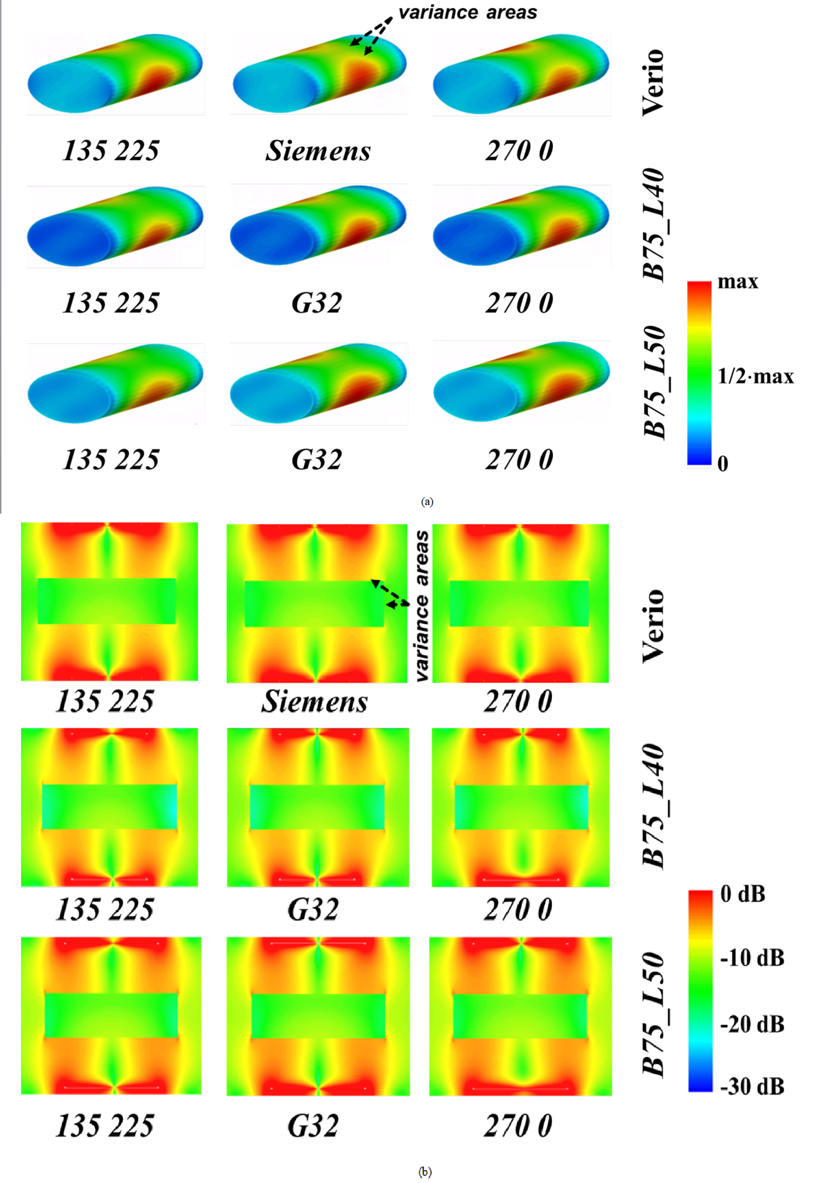
Fig. 3. Results for coils with 70 cm scanner bore. Each row is related to one coil geometry. Each column related to a given location of excitation ports, except the column with G32 design and Siemens port position. (a) Erms profile on external face of the oval phantom in linear scale, (b) Erms profile in air and in the oval phantom for XZ plane that is 75 mm below the iso-center in logarithmic scale. The level “-10 db” corresponds to maximum value of Erms inside phantom for this profile.
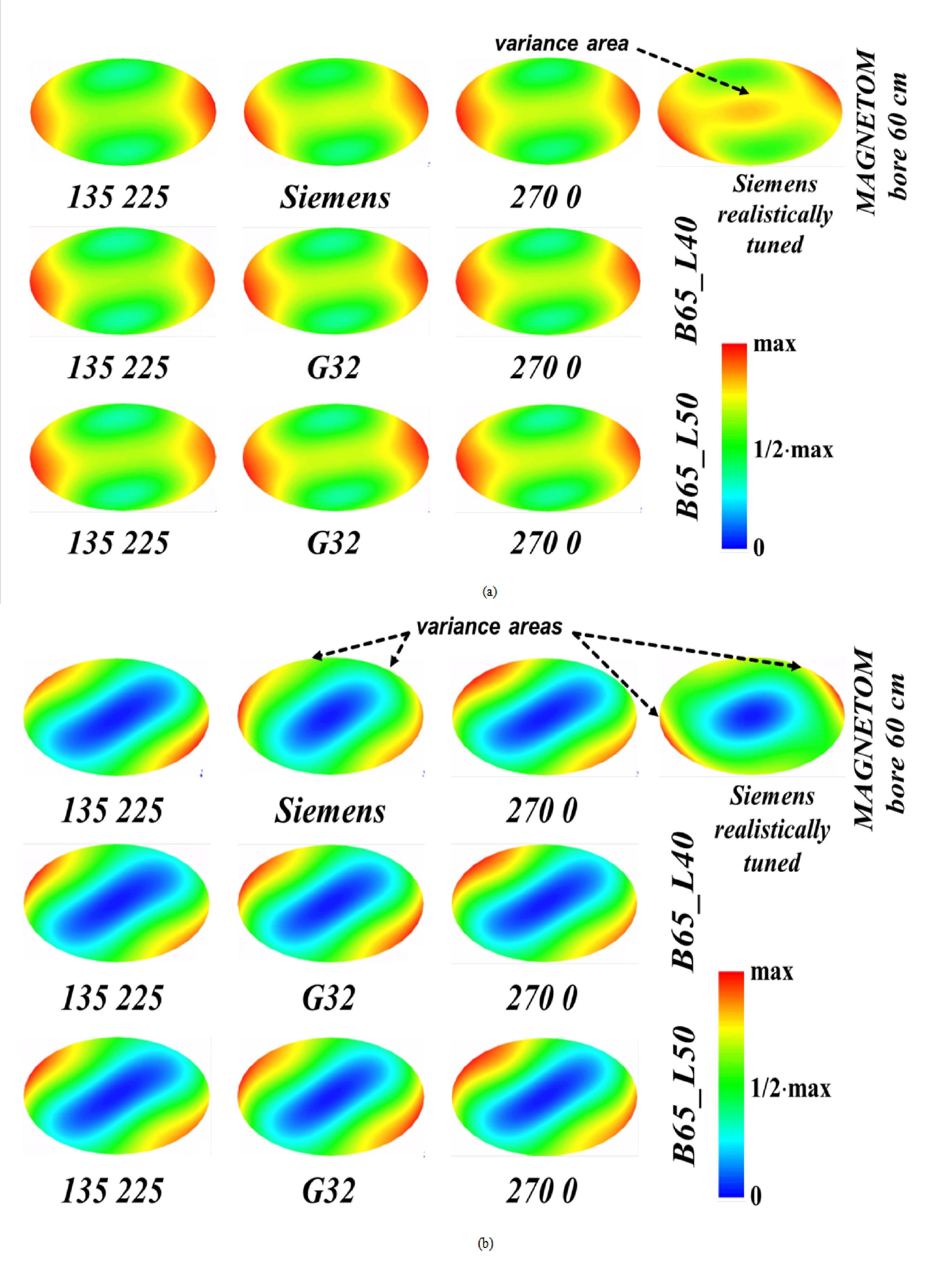
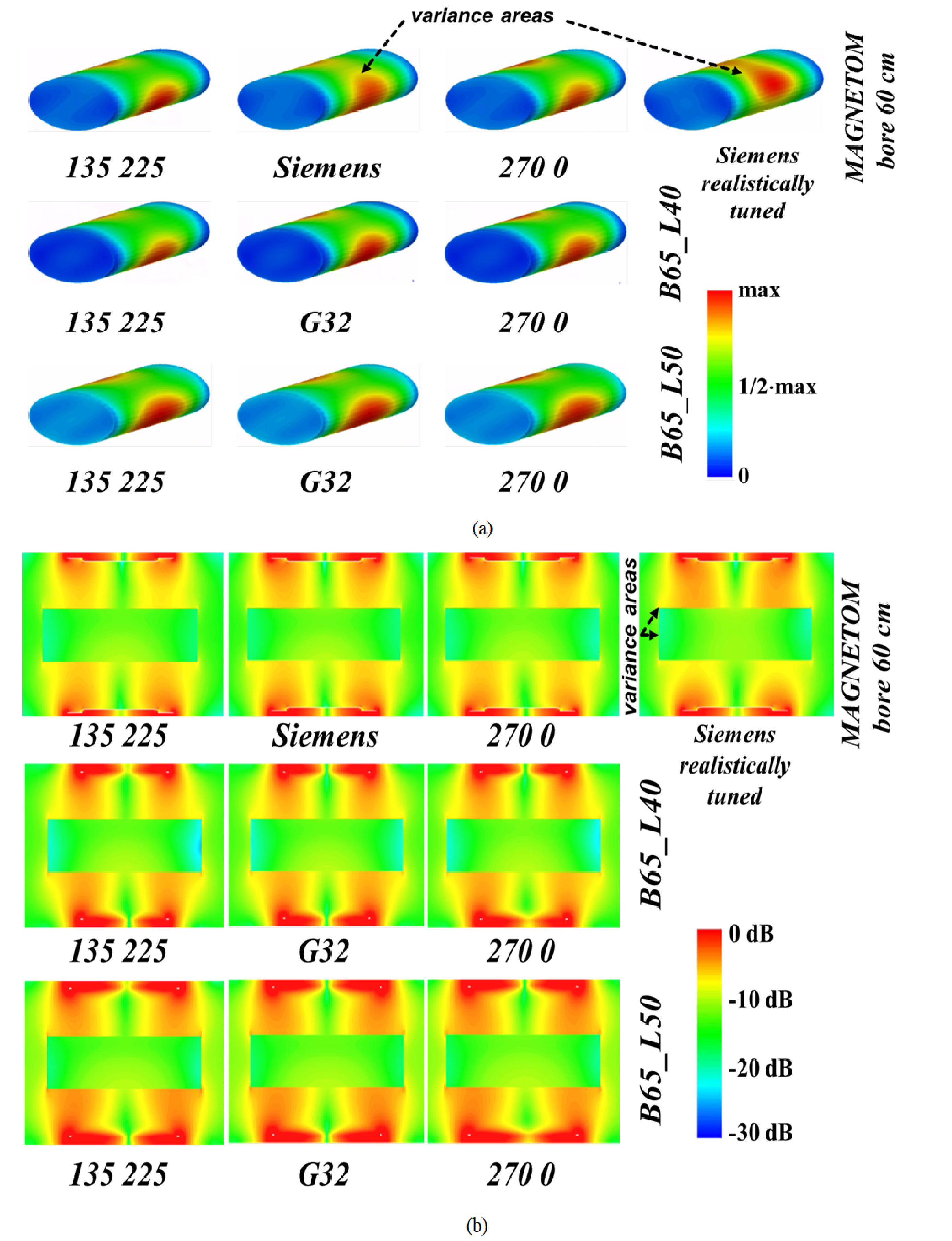
Fig. 5. Results for coils with 60 cm scanner bore. Each row is related to one coil geometry. Each column related to a given location of excitation ports, except the column with G32 design and Siemens port position. (a) Erms profile on external face of the oval phantom in linear scale, (b) Erms profile in air and in the oval phantom for XZ plane that is 75 mm below the iso-center in logarithmic scale. The level “-10 db” corresponds to maximum value of Erms inside phantom for this profile.