2629
When they go high, go low? (Maybe, but not so fast): Comparing RF heating of active implantable medical devices in 0.55 T vs. 1.5 T horizontal scanners1Department of Radiology, Northwestern University, Chicago, IL, United States, 2Department of Biomedical Engineering, Northwestern University, Evanston, IL, United States, 3A.A. Martinos Center for Biomedical Imaging, Department of Radiology, Massachusetts General Hospital, Charlestown, MA, United States, 4Harvard Medical School, Boston, MA, United States, 5Department of Neurosciences & Experimental Therapeutics, Albany Medical College, Albany, NY, United States, 6Department of Neurosurgery, Northwestern University, Chicago, IL, United States, 7Division of Cardiology, Department of Pediatrics, Northwestern University, Chicago, IL, United States, 8Department of Medical Imaging, Lurie Children's Hospital, Chicago, IL, United States
Synopsis
Low-field Magnetic Resonance Imaging (MRI) systems are gaining traction, but their impact on radiofrequency (RF) heating of elongated implants is unclear. The RF heating of conductive lead models with realistic trajectories was examined inside a 1.5 T MRI coil and a 0.55 T Wide Bore MRI coil. 0.1g-SAR was recorded at the tips of conductive implanted leads in adult patients with deep brain stimulation (DBS) systems and pediatric patients with cardiac implants, at both chest and head landmarks. In some instances, heating was higher in the 0.55 T coil, so caution must be exercised before promoting low-field coils as "implant-friendly".
Introduction
Recent advancements in magnetic resonance image reconstruction, improved electronics, and clearance of low-field MRI systems by the US Food and Drug Administration have sparked a rapidly increasing interest in using low and very-low field strength MRI systems [1]. Low-field MRI scanners have been most impactful in reducing cost and increasing ease of siting which is highly convenient in the new era of distributed imaging accelerated by COVID-19 pandemic [2]. Low-field also reduces susceptibility and off-resonance effects, making it even possible to image the lung [3]. Low-field MRI systems have also been widely promoted as “implant-friendly” albeit lacking evidence for such claims. This claim is highly concerning, because although the local SAR/B1+ ratio in the absence of implants is reduced at lower fields (due to the reduced electric field), the scenario can dramatically change in the presence of elongated implants due to the antenna effect [4]. Today, no data is available on RF heating of elongated implants such as leads in cardiovascular or neuromodulation devices in low-field scanners compared to high-field systems. Here we report results of the first simulation study comparing power deposition in the tissue around tips of deep brain stimulation leads in an adult population, and cardiovascular implanted electronic devices in a pediatric population during MRI in a 0.55 T MRI scanner versus a 1.5 T scanner. The purpose of this study is to verify whether 0.55 T reduces RF heating compared to 1.5 T as advertised.Methods
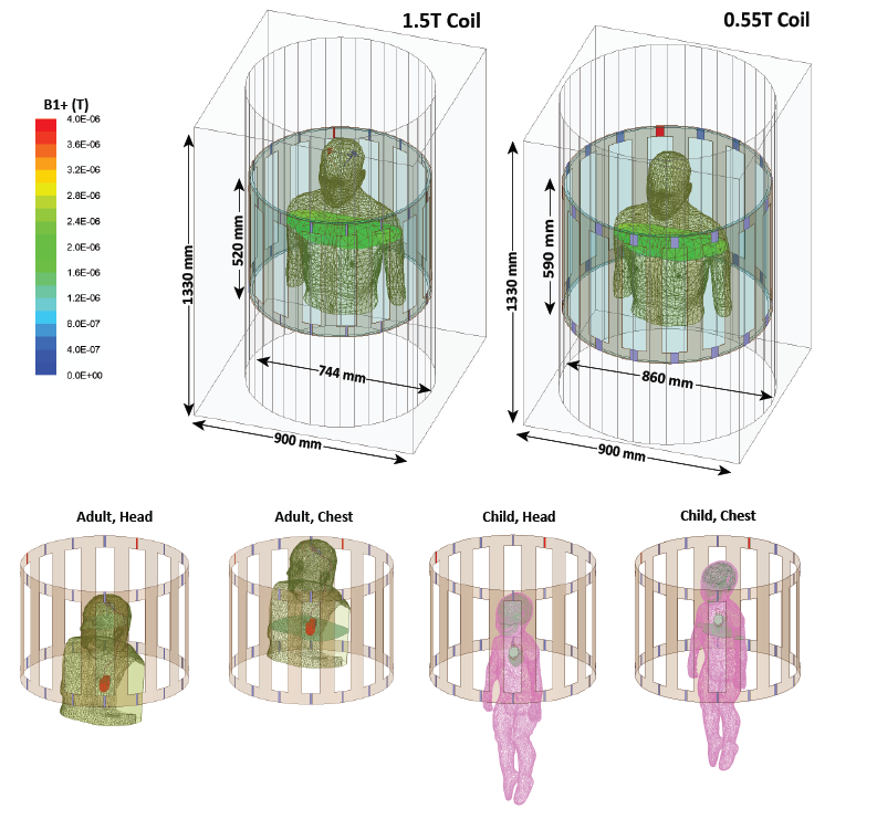
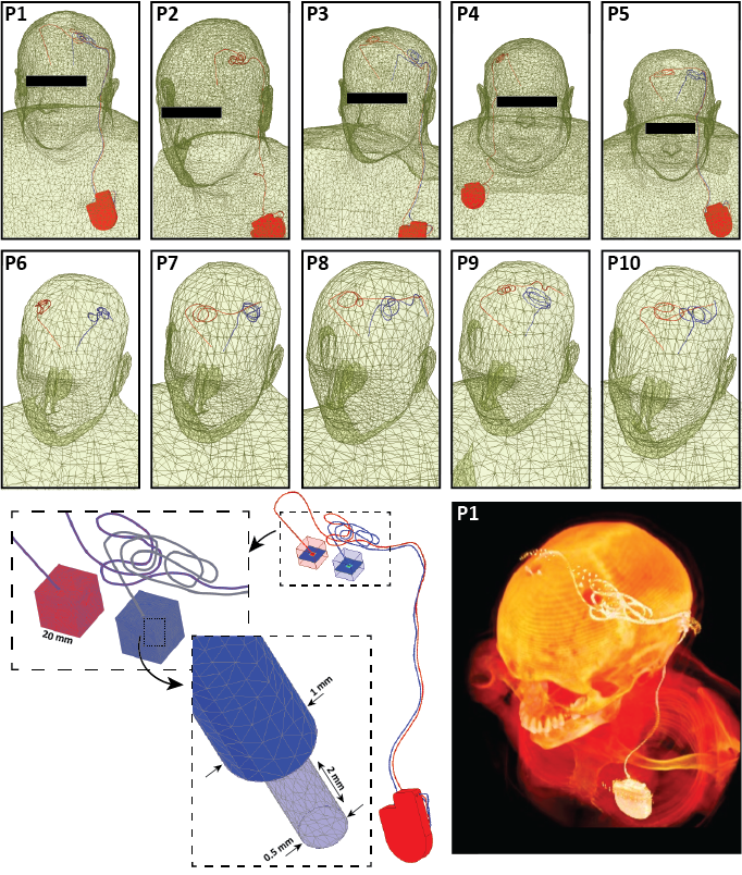
RF-coil models: Models of two circularly polarized high-pass RF body coils (16-rung) were constructed and tuned to 23 MHz (0.55 T) and 64 MHz (1.5 T) in ANSYS Electronics Desktop 2021 R1 (ANSYS Inc., Canonsburg, PA). Coil dimensions were chosen to mimic Siemens 1.5 T Aera and 0.55 T Free.Max systems.Patient populations and implant models: Three patient populations were studied: 1) adults with fully implanted deep brain stimulation (DBS) systems, 2) adults with lead-only DBS implants, and 3) children with cardiovascular implantable electronic devices (CIEDs). Patients with fully implanted DBS devices (5 patients, 8 leads in total) had a 40 cm lead with the tip implanted in the brain, which was connected to an implantable pulse generator (IPG) in the chest through a 60 cm extension analogous to Medtronic (lead 3387 and extension 3708660) and Abbott (lead 6172 and extension 6372) DBS systems. Patients with lead-only DBS implants (5 patients, 10 leads in total) only had a 40 cm lead with the tip implanted in the brain and the extracranial portion positioned on the skull following realistic trajectories. Lead trajectories and body models were created from segmented computed tomography (CT) images of patients operated for DBS surgery in our institution [5–8].
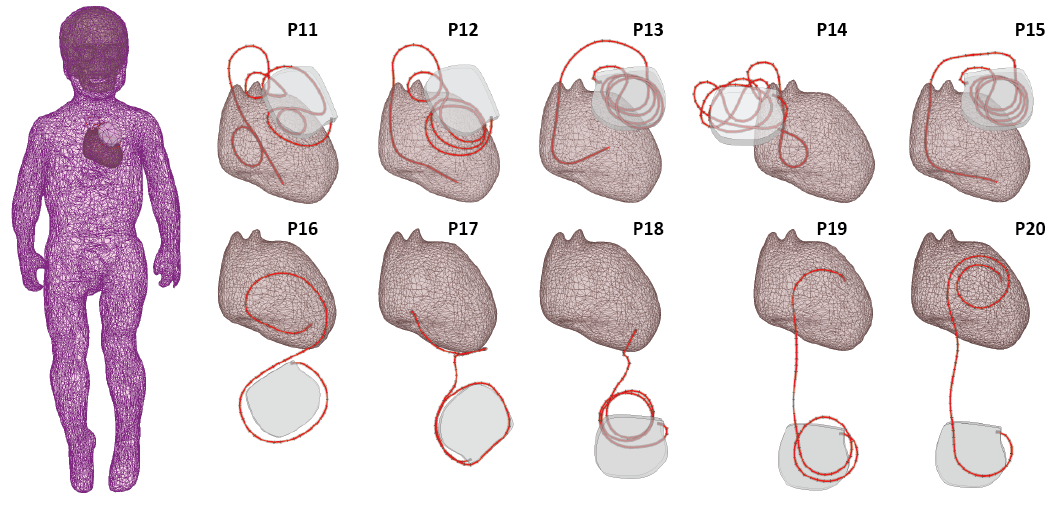
A pediatric body model was created from a segmented MRI of a 29-month-old child [9]. Ten unique CIED lead trajectories consisting of 5 35-cm epicardial leads and 5 58-cm endocardial leads were created based on surgical guidelines and radiographic images from previous publications and were incorporated in the body model.
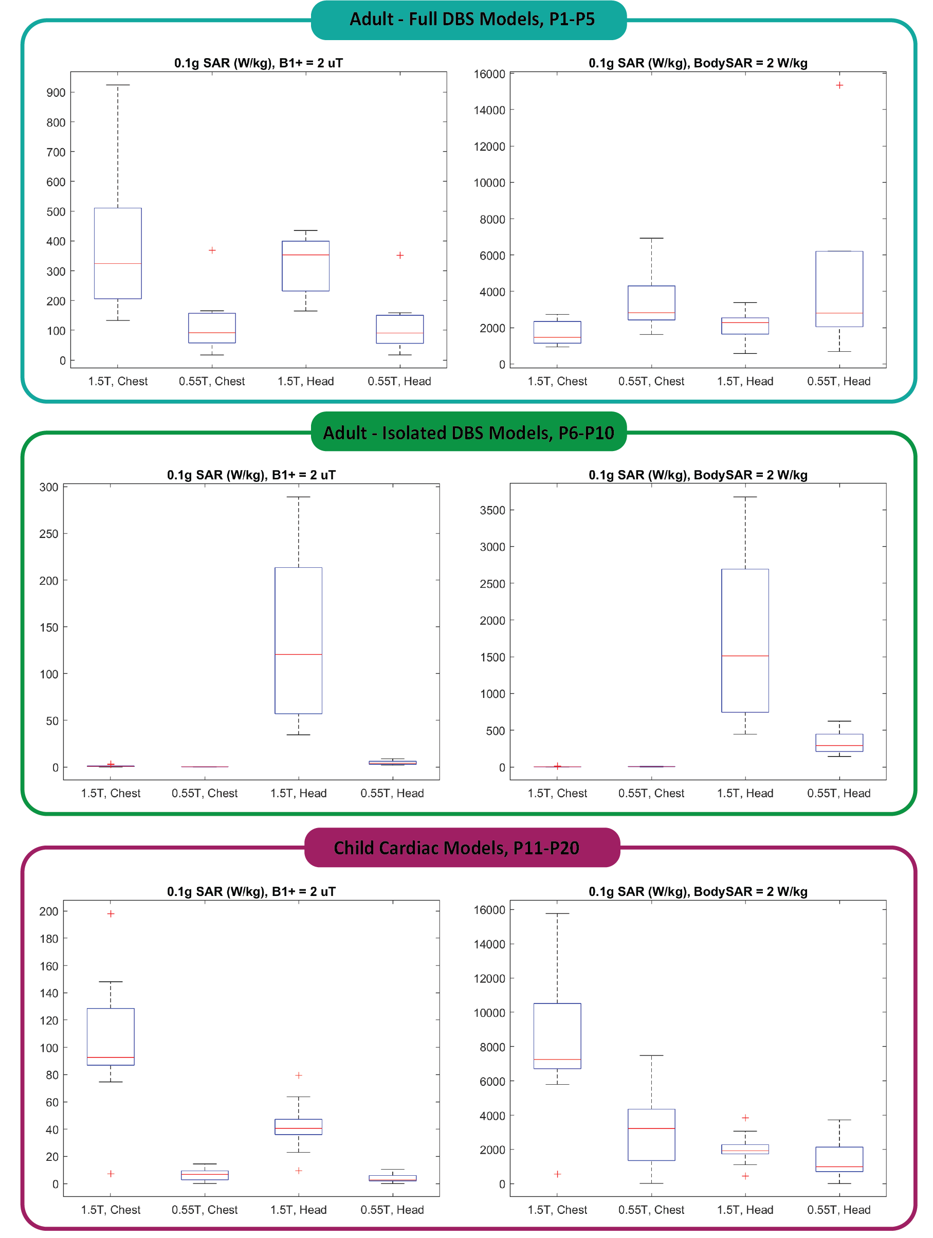
The maximum of a 0.1g-averaged SAR was calculated within a high-resolution mesh volume of 20mm x 20mm x 20mm cube surrounding the tips of implanted leads. The input power of both coils was adjusted according to two safety limits commonly imposed by device manufacturers: 1) to generate a mean B1+ = 2 μT on an axial plane passing through the isocenter of the coil, and 2) to generate the whole-body SAR of 2 W/kg.
Results
The half-wavelength of the RF field in the tissue was approximately 85 cm at 0.55 T and 30 cm at 1.5 T. When the length of the lead was substantially shorter than the half-wavelength in the tissue, the 0.55 T scanner produced lower local heating at the lead tips compared to the 1.5 T scanner. For example, the 0.1gSAR around tips of 40-cm lead-only DBS models was 335 ± 159 W/kg at 0.55 T and 1676 ± 1127 W/kg at 1.5 T for the head imaging landmark when input power of both coils was adjusted to produce a whole-body SAR of 2 W/kg. Similarly, for cardiac leads at chest landmark, 0.1gSAR was 3316 ± 2520 W/kg at 0.55 T and 8153 ± 4033 W/kg at 1.5 T when input power of both coils was adjusted to produce a whole-body SAR of 2 W/kg. However, when the conductor length was close to the half-wavelength of the RF field in the tissue, the 0.55 T scanner generated substantial heating. For the full DBS model (100 cm) at chest landmark, the 0.55 T scanner generated 0.1gSAR of 3458 ± 1824 W/kg at lead tips compared to 1701 ± 705 W/kg at 1.5 T when the power of both coils was adjusted to produce whole-body SAR of 2 W/kg.Conclusion
Caution should be exercised when attesting to the safety of low-field MRI in patients with implants. Although low-field scanners are often promoted as “implant-friendly”, they can generate substantial heating around elongated leads of active implantable medical devices.Acknowledgements
This work was supported by NIH grant R01EB030324.References
[1] Sarracanie M, Salameh N. Low-Field MRI: How Low Can We Go? A Fresh View on an Old Debate. Front Phys. 2020;8:172. doi:10.3389/fphy.2020.00172
[2] Heiss R, Nagel AM, Laun FB, Uder M, Bickelhaupt S. Low-Field Magnetic Resonance Imaging: A New Generation of Breakthrough Technology in Clinical Imaging. Invest Radiol. 2021;56(11):726-733. doi:10.1097/RLI.0000000000000805
[3] Campbell-Washburn AE, Ramasawmy R, Restivo MC, et al. Opportunities in Interventional and Diagnostic Imaging by Using High-Performance Low-Field-Strength MRI. Radiology. 2019;293(2):384-393. doi:10.1148/radiol.20191904524.
[4] Golestanirad L, Rahsepar AA, Kirsch JE, et al. Changes in the specific absorption rate (SAR) of radiofrequency energy in patients with retained cardiac leads during MRI at 1.5T and 3T. Magn Reson Med. 2019;81(1):653-669. doi:10.1002/mrm.27350
[5] Golestanirad L, Angelone LM, Iacono MI, Katnani H, Wald LL, Bonmassar G. Local SAR near deep brain stimulation (DBS) electrodes at 64 and 127 MHz: A simulation study of the effect of extracranial loops: Local SAR near DBS Electrodes. Magn Reson Med. 2017;78(4):1558-1565. doi:10.1002/mrm.26535
[6] McElcheran CE, Yang B, Anderson KJT, Golestanirad L, Graham SJ. Parallel radiofrequency transmission at 3 tesla to improve safety in bilateral implanted wires in a heterogeneous model: pTx at 3T to Improve Safety in Bilateral Implanted Wires. Magn Reson Med. 2017;78(6):2406-2415. doi:10.1002/mrm.26622
[7] Golestanirad L, Kazemivalipour E, Lampman D, et al. RF heating of deep brain stimulation implants in open‐bore vertical MRI systems: A simulation study with realistic device configurations. Magn Reson Med. 2020;83(6):2284-2292. doi:10.1002/mrm.28049
[8] Kazemivalipour E, Keil B, Vali A, et al. Reconfigurable MRI technology for low-SAR imaging of deep brain stimulation at 3T: Application in bilateral leads, fully-implanted systems, and surgically modified lead trajectories. NeuroImage. 2019;199:18-29. doi:10.1016/j.neuroimage.2019.05.015
[9] Jeong JW, Asano E, Juhász C, Behen ME, Chugani HT. Postoperative axonal changes in the contralateral hemisphere in children with medically refractory epilepsy: A longitudinal diffusion tensor imaging connectome analysis: Connectome Change after Epilepsy Surgery. Hum Brain Mapp. 2016;37(11):3946-3956. doi:10.1002/hbm.23287
Figures