2628
Excitation vector optimization for safe parallel transmission MRI of passively conducting implants in the presence of motion1MRI.TOOLS GmbH, Berlin, Germany, 2Berlin Ultrahigh Field Facility (B.U.F.F.), Max Delbrück Center for Molecular Medicine in the Helmholtz Association, berlin, Germany, 3Charité – Universitätsmedizin Berlin, berlin, Germany
Synopsis
MRI aided monitoring of (biodegradable) passively conducting implants is challenged by transmission field inhomogeneities and potential elevation of RF power deposition (SAR) in the vicinity of an implant. Small movements of an implant with respect to the RF transceiver constitute another potential risk factor for clinical MRI. Recognizing this challenge and the opportunities, this work uses a multi-objective genetic algorithm (GA) to examine the feasibility of excitation vector optimized parallel transmission in the presence of small variations in implant position/orientation. The GA approach provided excitation vectors that meet the safety guidelines for SAR in close vicinity of a (biodegradable) passively conducting implant and that are immune to small changes in the relative position between the implant and the RF transceiver. Our findings are not limited to the specific implant configurations and experimental setups used in this study but provide the technical foundation to derive a generalized transfer function.
Introduction
Non-invasive monitoring of implantation sites is of high clinical relevance to track patient recovery upon implant implantation. MRI of implants is challenged by implant-induced radio frequency (RF) constraints including B1+ inhomogeneities and SAR elevation1. Recognizing these constraints, established approaches focus on imaging regions outside of the implantation site and commonly put most weight on offsetting SAR constraints2. We previously implemented an optimized excitation vector approach3, which provides a solution for parallel transmission (pTX) that can address B1+ and SAR inhomogeneities for a known and fixed implant position. Recognizing this limitation this work examines the feasibility of optimized excitation vector pTX in the presence of small variations in implant position/orientation. This is of high relevance for clinical MR practice because the exact position of an implant may not be known a priori, or patient movement might induce shifts or rotations in implant position. These clinical challenges might render the excitation vector obtained for a preconditioned implant position/orientation sub-optimal and might obstruct implant monitoring.Material and method
Electromagnetic simulations using a custom-made eight-channel RF transceiver array composed of eight pairs of loops and fractionated dipoles4 in a modular configuration (figure1_a) were performed in CST studio suite (CST MWS, 2021) and further processed using in-house MATLAB scripts. The simulation setup consists of a cylindrical phantom (R=170mm, L=300mm) with muscle electrical properties at 300MHz. A cylindrical shape implant (R=2mm, L=70mm) mimicking a bio-degradable screw made of Magnesium was placed parallel to the phantom’s long axis. By aligning the origin of the coordinate system with the center of the phantom (figure1_b), the center of the implant was placed at (x=0, y=-55 mm, z=0). B1+ field optimization was performed using a multi-objective genetic algorithm (GA) with the goals to 1) maximize averaged B1+ in a target region of interest (ROI) while reducing the global maximum SAR in the whole simulation area, 2) minimize the B1+ inhomogeneity in the target ROI. The target ROI was defined by a cylinder (R=20mm, L=110mm) enclosing the implant. An optimum excitation vector (ev) derived from the GA approach, was used as a base ev and applied to scenarios where the implant is rotated and/or shifted with respect to its initial orientation/position. The scenarios used in the simulations are summarized in table1 where the position of the center of the implant is defined in Cartesian coordinates while orientations of the implant are defined by a spherical coordinate system. The resulting B1+ and SAR maps were calculated, and the performance of the method was benchmarked against a circular polarization (CP) shim vector.Result
Figure 2 shows transversal B1+ through the center of the implant and maximum projection point SAR maps obtained for GA and CP excitation vectors using the geometrical setups outlined in table 1. The target ROI encompassing the implant is highlighted with a black contour. CP B1+ shimming suffers from deficient B1+ in the vicinity of the implant due to strong signal voids in this region. From the safety perspective, the CP induces significant SAR elevation close to the implant tips which may result in hazardous risks of tissue burn. The optimized shim pattern derived from GA was able to eliminate the B1+ inhomogeneities for several implant orientations. The GA approach also yielded only minor SAR elevation close to the implant. Figure 3 demonstrates that the GA approach outperformed the CP approach for B1+ and SAR. In detail, the extreme case of the geometrical setup 5 (θ=70, φ=-450) showed a maximum point SAR generated by the CP approach which was 709% higher than the maximum point SAR facilitated by the GA approach. For the same setup, the mean B1+ provided by the CP approach was 30% inferior to that supported by the GA approach.Discussion and conclusion
MRI aided monitoring of implantation sites requires an RF shim pattern with a uniform strong B1+ in the vicinity of the metallic. At t the same time SAR induced by the implant must be kept within the safety limits. Achieving this goal using the GA approach should not be limited to fixed implant positions but needs to be adapted to and evaluated for real-world clinical scenarios including implant rotation or shift. To address this challenge, this work examined the propensity of GA-driven shimming pattern for relative movements of an implant with respect to the position of RF transceiver using a fixed excitation vector. Our results underline that B1+ and SAR induced by an excitation derived from the CP approach depends on the relative position between the implant and the RF transceiver. This observation compromises safe measurement planning for implant monitoring. Unlike the CP approach, GA-driven excitation vectors provide strong and uniform B1+ in the target ROI. The GA approach provided excitation vectors that meet the safety guidelines for SAR in the close vicinity of a (biodegradable) passively conducting implant and that are immune to small changes in the relative position between the implant and the RF transceiver. Our findings are not limited to the setups used in this study but provide the technical foundation for deriving a generalized transfer function.Acknowledgements
This project is supported by the H. 2020 European Training Network of the European Union (MgSafe, grant agr. No. 811226)References
[1] Review Physics of Implant Heating,” pp. 1–20, 2020, doi: 10.1002/jmri.27194.
[2] L. Winter et al., “Parallel transmission medical implant safety testbed: Real-time mitigation of RF induced tip heating using time-domain E-field sensors,” Magnetic Resonance in Medicine, 2020, doi: 10.1002/mrm.28379.
[3] M. Berangi, A. Kuehne, T. Niendorf “Safe 7T MRI of tissues neighboring Mg-based biodegradable implants using parallel transmission” ISMRM 2021: https://www.ismrm.org/21/program-files/O-68.htm
[4] A. J. E. Raaijmakers et al., “The fractionated dipole antenna: A new antenna for body imaging at 7 Tesla,” Magnetic Resonance in Medicine, 2016, doi: 10.1002/mrm.25596.
Figures
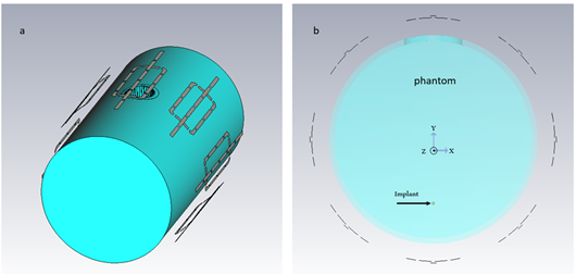
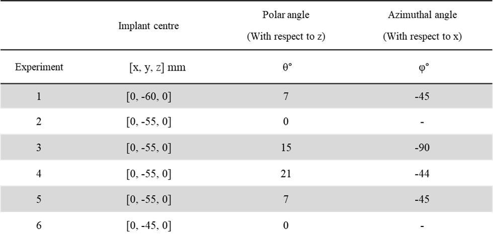
Table 1: Experimental setups used for the EMF simulations. Each setup is defined by the position of the center of the implant and its orientation using polar and azimuthal coordinate.
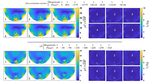
Figure 2: B1+ maps (left) and maximum projection maps of point SAR (right) derived from the GA approach (top row) and the CP approach bottom row) using the experimental setups 1-6.
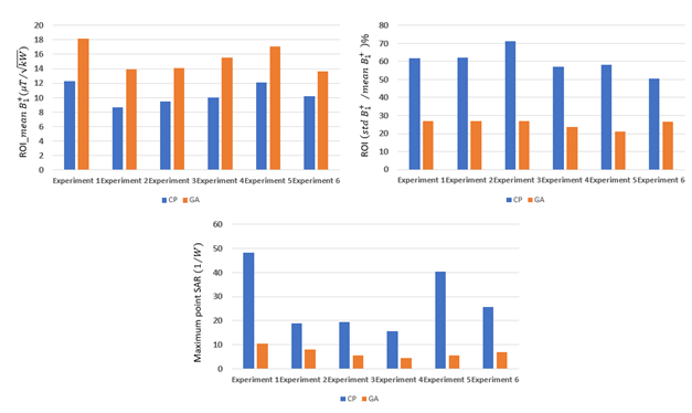
Figure 3: Top row) Mean and coefficient of variation of B1+ in the target ROI obtained for the GA and CP transmission field shimming modes for the experimental setups 1-6.. Bottom row) Maximum point SAR obtained from the entire phantom using the GA and CP excitation vectors.