2625
Combined RF & Gradient Injection Network for AIMDs with leads
Vincent Hammersen1, Michael Wolff2, Andreas Rennings3, and Gregor Schaefers1,2
1MRI-STaR GmbH, Gelsenkirchen, Germany, 2MR:comp GmbH, Gelsenkirchen, Germany, 3General and Theoretical Electrical Engineering (ATE), University of Duisburg-Essen, Duisburg, Germany
1MRI-STaR GmbH, Gelsenkirchen, Germany, 2MR:comp GmbH, Gelsenkirchen, Germany, 3General and Theoretical Electrical Engineering (ATE), University of Duisburg-Essen, Duisburg, Germany
Synopsis
MR safety of AIMD with leads is assessed test procedures defined in ISO/TS10974. This separates the different electromagnetic field interactions into independent test procedures. E.g., malfunction and rectification testing, with gradient and RF injection networks connected to the lead ports of AIMDs. But this does not correspond to "realistic MRI exposures", where a precise combination of RF and magnetic fields is used for imaging. For this reason, a concept is being proposed in which both injection networks are combined to allow a concerted exposure. This allows the simultaneous exposition of any gradient and RF signal combination.
INTRODUCTION
Testing of active implantable medical devices (AIMDs) for MR safety is performed according to the procedures defined in ISO/TS 109741. These procedures are separated in different physical hazards, which are investigated mostly independently from others. This also applies to the testing of AIMDs with electrically long leads, for RF-induced malfunctions or rectification products (Clause15), as well as for gradient-induced malfunctions or extrinsic potentials (Clause16 and 13). In these clauses the devices main bodies are exposed to, previously determined, worst-case test levels by connecting their electrode lead entry points via so called injection networks. Although the approach of these isolated worst-case exposures is already well implemented in testing routines, this separation does not represent a “realistic” clinical case, as MR imaging relies on a precise combination of RF and Gradient exposures. Out of this context, this study presents a concept for a combined RF & Gradient injection network. By applying this, the worst-cases of both test methods can be applied simultaneously, as well as the impact of "realistic" MR pulse sequences on AIMDs can be investigated.METHODS
The injection networks are described in the ISO/TS 10974 and consist of several components, which are connected to the DUT via 50Ω lines (cf. Fig1). For the RF injection network these components are typically: 1. signal sources & amplifiers; 2. circulators or attenuators to prevent reflections; 3. splitters for multiple single electrode lines in common mode; 4. couplers for power input and output monitoring and 5. bias tees to separate the ingoing RF and rectified DC power. Potential rectified power levels are monitored via an oscilloscope at the DC port of the bias tees. The network for reproducing the gradient induced power levels in the DUT typically consist of: 1. Signal source; 2. a tissue interface network for monitoring the AIMD response; 3. a tissue simulating impedance (standard 250 Ω) and 4. For detecting the extrinsic potential a 1 MΩ differential probe is connected to the input line and the return line/AIMD casing. Given that the bias tees are the last component of the RF network and separate high- and low-frequency components, it is an uncomplicated solution to use them as a connector for the combined gradient and RF network. A combined network creates the possibility to expose the AIMD to any combination of low and high frequency test signals (shape, duration, magnitude, phase shift). This also includes "realistic MR sequences". MR sequence diagrams can be converted into electrical induction timing sequence for gradient and RF power exposition. To cover the combined malfunction tests, suitable gradient and RF levels must be applied simultaneously over the defined exposure time. The differential probe used for detecting the extrinsic potentials and charges of Clause 13 can also be used to measure the RF-power rectified products of Clause 15. To illustrate the applicability (see Fig2), a full-wave rectifier consisting of 4 diodes was used as dummy, to rectify gradient (10kHz) as well as RF-frequencies (64 MHz). A 64 MHz square wave pulse and a burst of 6 consecutive 10 kHz square wave pulses with negative bias were used as the test signal.RESULTS
The concept proven to be solid, and the combinations and magnitude phase shifts of the combined injected test signals is only limited by the power ratings of the network components and the technical specifications of the arbitrary waveform generators.With the voltage bias of the gradient 10 kHz square signal the required minimum voltage of 0.7 V of the Si diodes (cf. Fig 2) was exceeded and a rectification of the RF signal of approx. 100 mV could be observed (red) for the rest of the RF pulse. This rectification could be confirmed by the decreased power levels observed by the bidirectional coupler for the reflected RF signal (blue) and, remarkably, also for the forward signal (green). However, as can be seen from the gradient input monitor signal (yellow) and the voltage across the tissue resistor (red), there were voltage spikes of unknown origin at the starting flank of the square pulses.DISCUSSION
The otherwise separately evaluated response of a DUT to injected gradient and RF signals can be easily coupled via bias tees. This allows the generation of a “concerted worst-case" situation. The standard long-term exposure of 30 minutes for combined malfunction checks is possible, especially since the monitoring ports of the networks remain in place. With the aid of a dummy, it can be shown that rectified RF can also be measured at the tissue resistance using a 1 MOhm test probe. This is different from the standard measurement of RF rectification products at the DC port of the bias tee at 50 Ω. Also, the impact of the reflected 64 MHz signal at the tissue resistance is missing. However, for this purpose it is possible to replace the bias tee with a simple DC block and a 50 Ω coaxial Tee connector (cf. Fig 3). Although only one combined injection line was used for demonstration purposes, it is possible to use any number of lines to contact each electrode of the AIMD individually. By phase shifting single or multiple lines, differential exposure analysis could also be performed.Acknowledgements
No acknowledgement found.References
1. Technical specification ISO/TS 10974:2018 “Assessment of the safety of magnetic resonance imaging for patients with an active implantable medical device”. The International Organization for Standardization. 2018.Figures
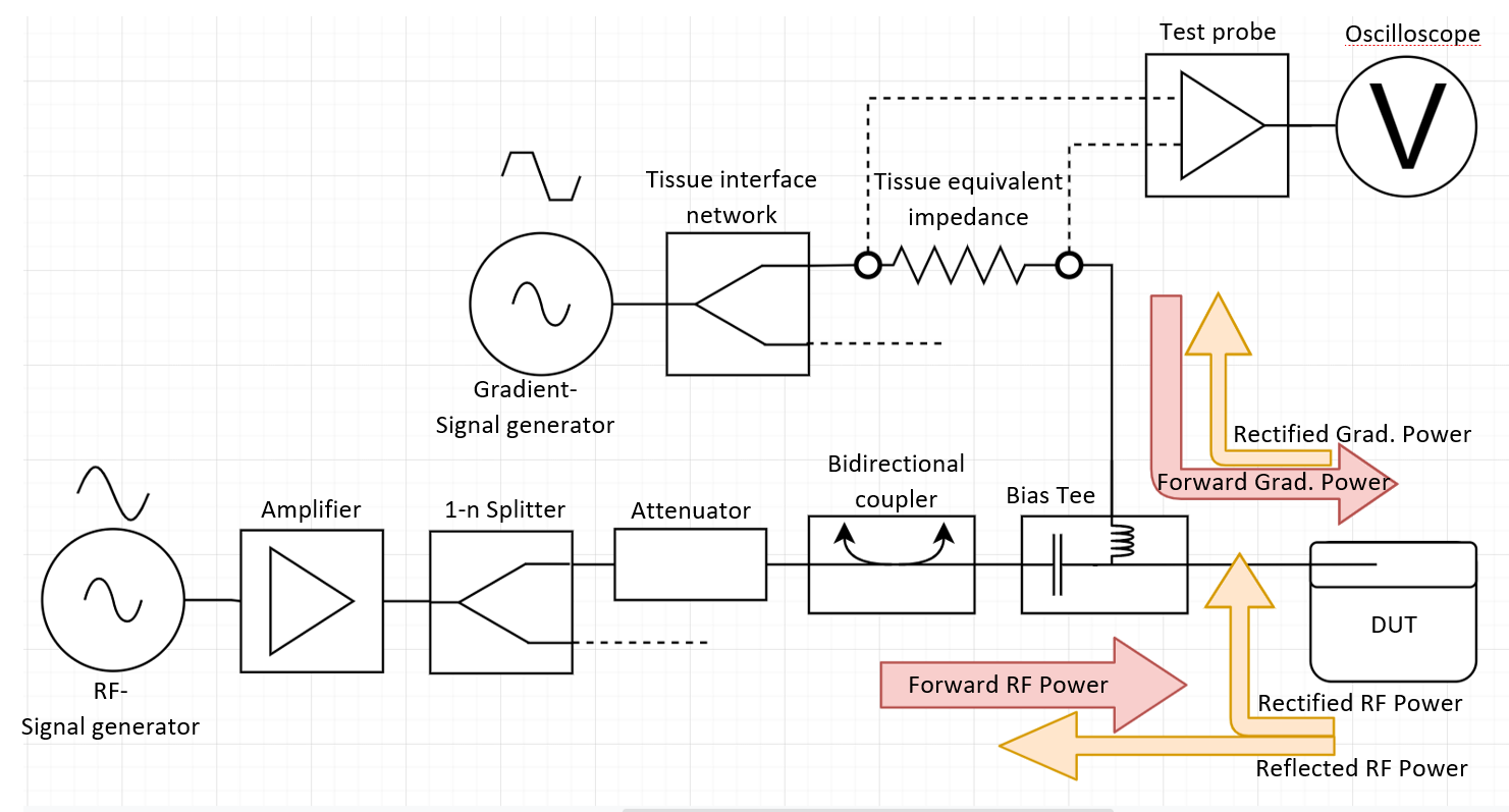
Schematic
of the combined RF & gradient injection network and associated power flow.
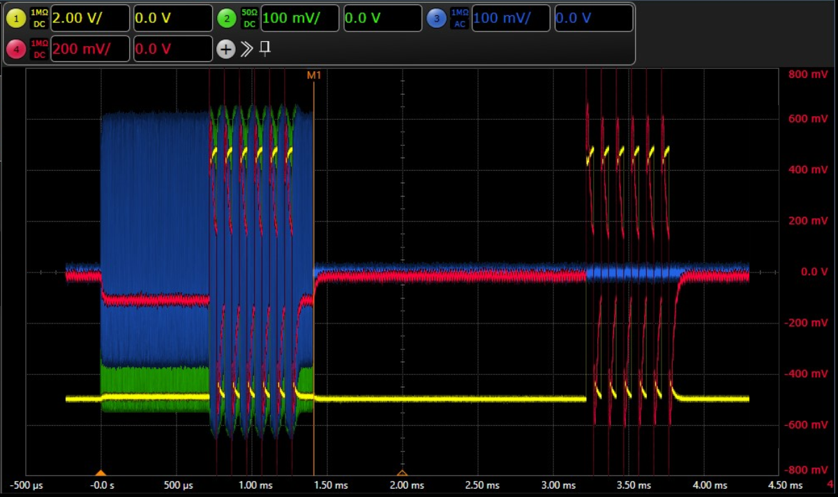
Monitored
test voltage levels applied on the dummy (different scaling levels). Green:
64MHz RF-Input signal; Blue: reflected 64MHz signal; Yellow: monitored gradient
Input levels; Red: forward and rectified (Gradient & RF) voltage at
the 250Ω tissue impedance. The rectitifed voltage is slightly lower with an
active RF-pulse. Also, energy dissipation due to rectification is visible at
the reflected RF signal (blue) directly after 10kHz gradient square pulse.
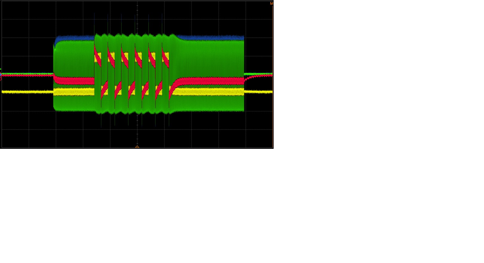
DC-Block and Tee connector type power splitter:
Monitored test voltage levels with full wave rectifier dummy. Blue: RF forward
RF power; Green: reflected RF power; Yellow: gradient input monitor: Red: forward
and rectified (Gradient & RF) and parts of the reflected RF voltage at the 250Ω
tissue impedance.
DOI: https://doi.org/10.58530/2022/2625