2624
Significance of Covering Anatomical Variations for Conservative Assessment of Deposited Power of Leaded Implants in Patients1IT'IS Foundation, Zurich, Switzerland, 2Department of Information Technology and Electrical Engineering, ETH Zurich, Zurich, Switzerland, 3Center for Devices and Radiological Health (retired), FDA, Silver Spring, MD, United States
Synopsis
Anthropomorphic computational phantoms are used to numerically estimate the potential envelope of intensity and distribution of induced E-fields in patients undergoing MR examination. The impact of anatomical variation of the phantom on medical implant risk assessment is demonstrated for generic transfer functions and lead trajectories representing pacemaker, DBS, SCS, and cochlear implant routings. Results showed that even when only one generic transfer function was considered, each of the 12 anatomical phantoms represented the worst-case for at least one configuration. Thus, the widest available range of anatomical phantoms must be examined to define a conservative safety envelope.
Introduction
Safety assessment of radiofrequency (RF) induced heating during magnetic resonance (MR) examination of active implantable medical devices (AIMD) according to ISO 109741 is performed by evaluating the response of the implant transfer function to tangential electrical (E-)fields along implant trajectories. IMAnalytics (ZMT Zurich MedTech AG, Switzerland) together with the precomputed MRIxViP field library2,3 is a computational modeling Medical Device Development Tool (MDDT) qualified by the U.S. Food and Drug Administration for MR safety evaluations. MRIxViP includes 12 Virtual Population (ViP) anatomical phantoms, 20 two-channel RF coil models (10 each at 64 MHz and 128 MHz), and imaging positions from head to lower legs, to extract tangential E-fields along defined routings and calculate the response of the implant transfer function to determine the deposited power at the implant electrode array.In this study, we investigated the variability of highest deposited power in all ViP models at all imaging positions depending on the implant trajectories for a standard implant. Specifically, the objective was to determine whether a single or a small set of generic anatomical models with specific characteristics always yields the worst case of RF-induced heating, or whether a wide range of models covering the population is needed to conservatively estimate risk.
Methods
To investigate the impact of a diverse selection of body models for the assessment of Tier 3 RF heating of AIMD using IMAnalytics with MRIxViP and BCLib, the following 12 ViP models currently included in the MRIxViP library were selected: Billie, Duke, Eartha, Ella, Ella BMI-26, Ella BMI-30, Fats, Fats BMI-29, Glenn, Louis, Thelonious, and Yoon-sun2,3. These models cover a range of the general population with respect to age and BMI4,5 (Figure 1). The implants studied covered five types of generic implant routings: pacemaker leads, deep brain stimulators (DBS), spinal cord stimulators (SCS), and intra- and extracochlear leads. For the electrically long leads (pacemaker, DBS, SCS), 100 different example routings were placed in each ViP model. To cover the different MRI excitations or the case of head-first vs. feet-first imaging, we distinguished between the left and right side of the model. For the intra- and extracochlear implant trajectories, five sample trajectories were implemented per side, and the left- and right-side results were combined. Figure 2 shows an example of the routings in ViP phantom Duke. The tangential E-fields along the routings were extracted with IMAnalytics for MR operation at Normal operating mode (SAR limits calculated for each RF coil, patient, and landmark) in circular polarization (CP) with head-first scanning.While a transfer function is unique to the implant design (IPG layout, lead length, electrode array), the transfer function of the generic implant SAIMD-U1 (ZMT) was used for the purpose of comparability between the different ViP models and routings. The SAIMD-U is shown in Figure 3 (a) and the corresponding transfer functions at 64 MHz and 128 MHz in 3 (b).
Results
Figure 4 and 5 summarize the normalized distributions of highest deposited power over all configurations for each implant routing group and ViP model, as a function of imaging landmark (head to lower legs) at 64 MHz and 128 MHz, respectively.At 64 MHz, the highest deposited power of the pacemaker is observed in Ella BMI-30 for the left-, and in Glenn for the right-side routings. Similarly, for the left-side DBS routings, Ella BMI-30, and for the right-side, Billie result in the highest deposited power. In the case of the SCS, the highest deposited power is predicted in Billie, but depending on the imaging position, it could occur in Yoon-sun. Yoon-sun also represents the worst case for both the intra- and the extracochlear routings at 64 MHz, by up to 1 dB. The peak landmark in terms of deposited power is seen to be consistent across anatomical phantoms.
At 128 MHz, the predicted highest deposited power within different ViP models shows greater variability depending on the imaging position. For the pacemaker path, the worst case on the left-side is Ella BMI-30 and on the right-side routing Yoon-sun. When considering head imaging positions for left-side implant trajectories, Billie shows higher deposited power than Ella BMI-30. The left-side DBS routings showed high variability in head/neck imaging positions, while the right-side DBS routing was consistently highest in Fats. A large amount of variability in worst-case prediction is also given for the SCS trajectories, depending on the side and the imaging position. A similar trend is observed for cochlear routings. The peak landmark in terms of deposited power was less consistent across anatomical phantoms at 128 MHz.
Conclusion
This study investigated how the use of a wide range of computational anatomical models affects the risk assessment of MR examination of patients with AIMDs. Depending on the implant type and location, and the imaging landmark, the maximum deposited power could occur in any of the 12 anatomical models, even when considering only one generic transfer function. This variability supports the fact of a large anatomical dependence of the induced fields, which are difficult to predict, and therefore the safety of patients with implants is best warrantied when a large number of independent anatomical models are evaluated when defining the safety envelope of MR compatibility of AIMD.Acknowledgements
No acknowledgement found.References
1. ISO. Assessment of the safety of magnetic resonance imaging for patients with an active implantable medical device, Technical Report 10974:2018, International Organization for Standardization, Geneva, Switzerland.
2. Christ A, Kainz W, Hahn E, et al., The Virtual Family – Development of Surface-based Anatomical Models of Two Adults and Two Children for Dosimetric Simulations, Physics in Medicine and Biology, 2010, 55(2); 23-38.
3. Gosselin MC, Neufeld E, Moser H, et al., Development of a New Generation of High-Resolution Anatomical Models for Medical Device Evaluation: The Virtual Population 3.0, Physics in Medicine and Biology, 2014; 59(18), 5287–5303.
4. Ogden CL, Carroll MD, Kit BK, Flegal KM. Prevalence of childhood and adult obesity in the United States, 2011-2012. JAMA. 2014;311(8):806-14
5. Ogden CL, Fryar CD, Carroll MD, Flegal KM. Mean body weight, height, and body mass index, United States 1960-2002. Adv Data. 2004;(347):1-17
Figures
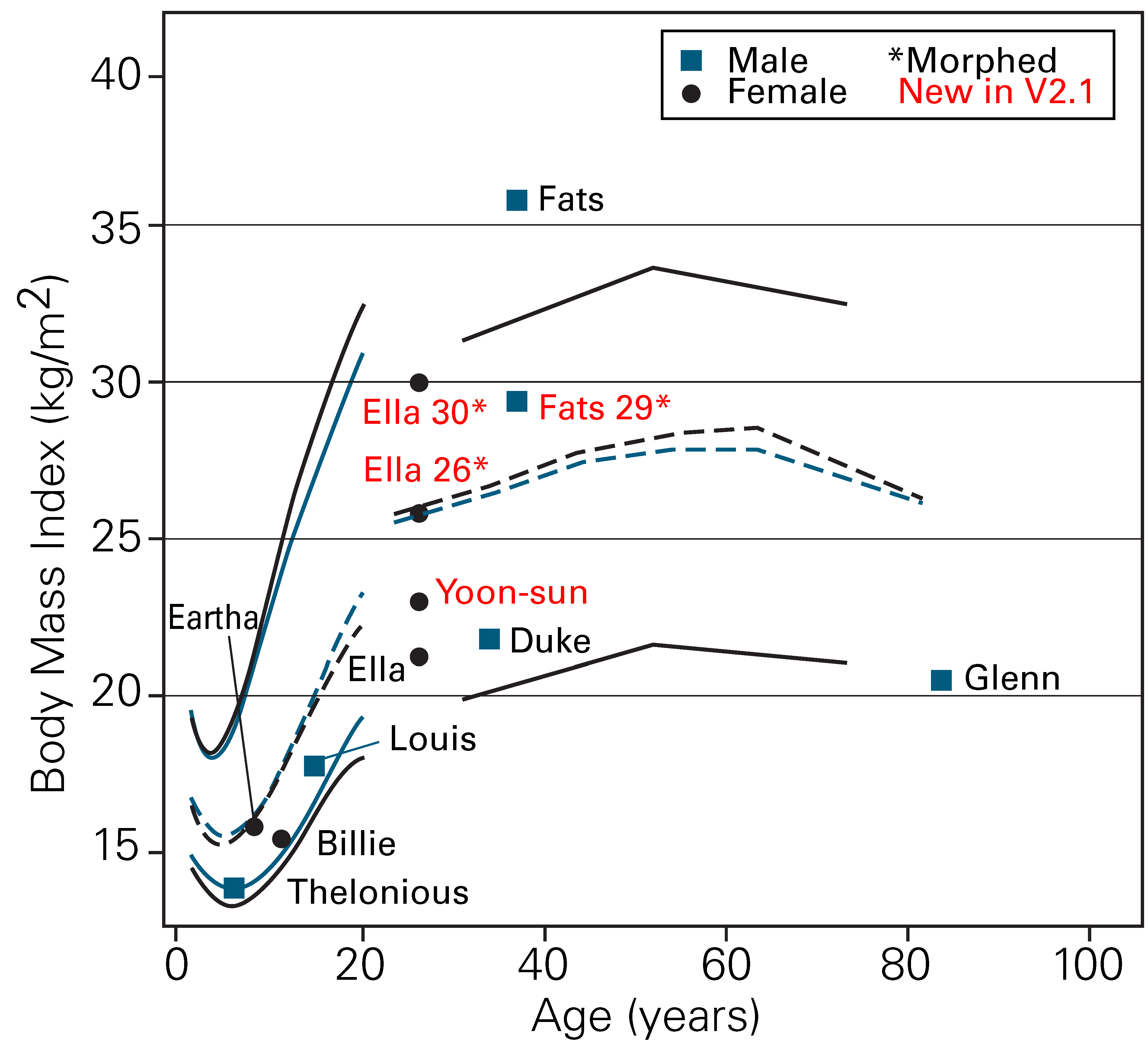
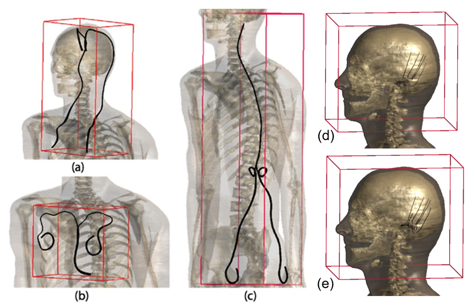
Figure 2: Sample trajectories in ViP2,3 model Duke for (a) DBS, (b) pacemaker, (c) SCS, (d) intracochlear, (e) extracochlear AIMD.
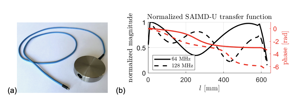
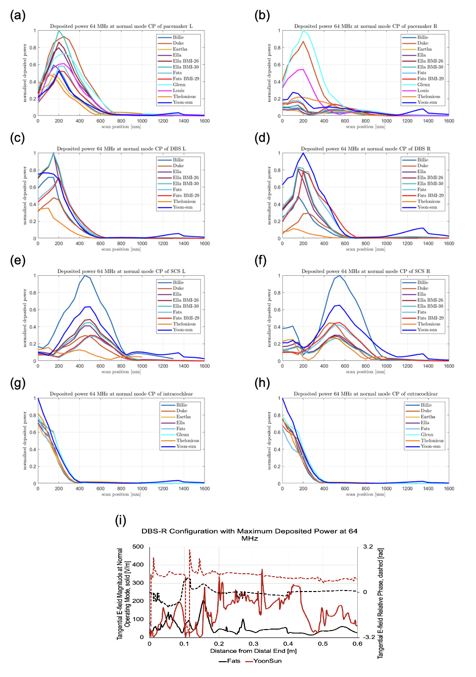
Figure 4: Maximum deposited power prediction with respect to MR imaging position (0 mm is the center of the head) for different implant routings in the MRIxViP population under 1.5 T MR exposure in normal mode from 10 RF coils. (a) left and (b) right side pacemaker, (c) left and (d) right side DBS, (e) left and (f) right side SCS, (g) extracochlear and (h) intracochlear implant. (i) Example of tangential E-fields a long DBS right side configuration resulting in maximum deposited power in Fats and Yoon-sun.
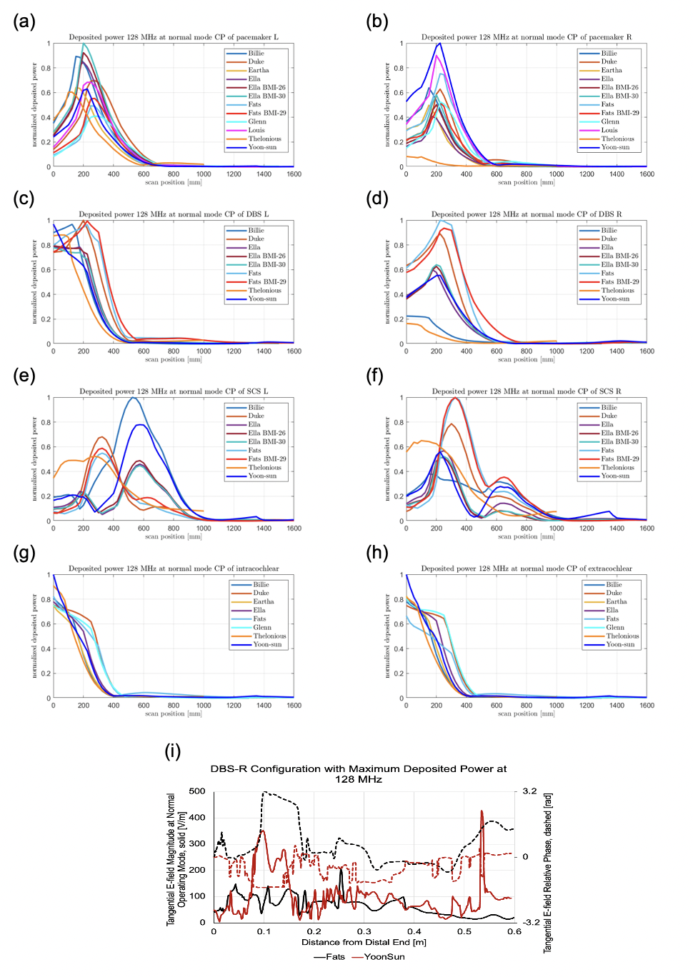
Figure 5: Maximum deposited power prediction with respect to MR imaging position (0 mm is the center of the head) for different implant routings in the MRIxViP population under 3.0 T MR exposure in normal mode from 10 RF coils. (a) left and (b) right side pacemaker, (c) left and (d) right side DBS, (e) left and (f) right side SCS, (g) extracochlear and (h) intracochlear implant. (i) Example of tangential E-fields a long DBS right side configuration resulting in maximum deposited power in Fats and Yoon-sun.