2622
Deep brain stimulation patient safety: Effects of patient-based lead trajectories on full-body 3 T MRI1Physical Sciences, Sunnybrook Research Institute, Toronto, ON, Canada, 2Medical Biophysics, University of Toronto, Toronto, ON, Canada, 3Surgery, University of Toronto, Toronto, ON, Canada
Synopsis
High SAR RF pulse sequences continue to be avoided for patients with implanted deep brain stimulation (DBS) devices, due to the increased risk of injury. Recent studies have shown that DBS lead management can impact electromagnetic behavior and thus, the overall RF heating effects along the implanted device. The present work studied two patient-based DBS lead trajectories using a commercial DBS device with MR-conditional labeling for full-body 3 T MRI, implanted in a novel anthropomorphic phantom. The preliminary results showed temperature elevations that exceed current imaging guidelines remains possible for high SAR RF pulse sequences.
Introduction
Magnetic resonance imaging (MRI) safety of deep brain stimulation (DBS) patients at 3 T remains a challenge. Although progress has been made, clinical researchers continue to avoid radiofrequency (RF)-intensive pulse sequences, such as spin-echo imaging, due to increased risk of injury1. It is well documented that the DBS electrode tips are associated with the highest risk of RF heating, but recent simulation studies have suggested potential risks at other locations along a lead trajectory, and reduced risk reduction from careful lead trajectory management2,3. New MRI safety experiments are needed to investigate these issues. Furthermore, there has been recent technological advancement in commercially available DBS devices, with the Medtronic Percept PC device becoming the first of its kind to be granted MR-conditional labeling for full-body 3 T MRI, in 20204. The present work thus involves a series of MRI RF heating experiments with the Percept PC DBS device implanted in a novel anthropomorphic phantom using two patient-based DBS lead trajectories4,5. The preliminary results demonstrate that the potential risk of elevated temperatures (exceeding present MRI guidelines6) still remains for high specific absorption rate (SAR) RF pulse sequences, and that additional research will be needed to achieve safe unrestricted 3 T MRI with such devices in the future.Methods
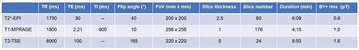
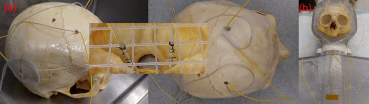
MRI RF heating experiments were conducted on a 3 T Siemens MRI system (Magnetom Prisma, Siemens, Erlangen, GER) using the standard body coil for RF transmission and the standard 64-channel head and neck coil for RF reception. Three MRI pulse sequences were used, ranging from low to high RF power, as listed in Figure 1. RF heating experiments were conducted using two DBS lead trajectories that reasonably represented the surgical procedures at Toronto Western Hospital (Toronto, CAN) and Sunnybrook Health Sciences Centre (Toronto, CAN), in the anthropomorphic phantom as shown in Figure 2. The MRI study was conducted over two imaging sessions that tested each DBS trajectory on separate days. The Medtronic Percept PC device (B35200, Medtronic, Dublin, UK) with DBS leads (3387, Medtronic, Dublin, UK), approved for MR-conditional full-body 3 T MRI, was used bilaterally and powered off throughout. Four fibre-optic temperature sensors (T1, Neoptix, Quebec City, CAN) were used, secured at the tips of each DBS electrode, the DBS lead loop geometry (i.e. the ear and skull blur hole) and the deep surface of the implanted pulse generator (IPG). These secondary locations were selected according to our previous studies1. Temperature measurements (±0.2⁰C accuracy) were recorded at 1 Hz for the full duration of each pulse sequence.Results
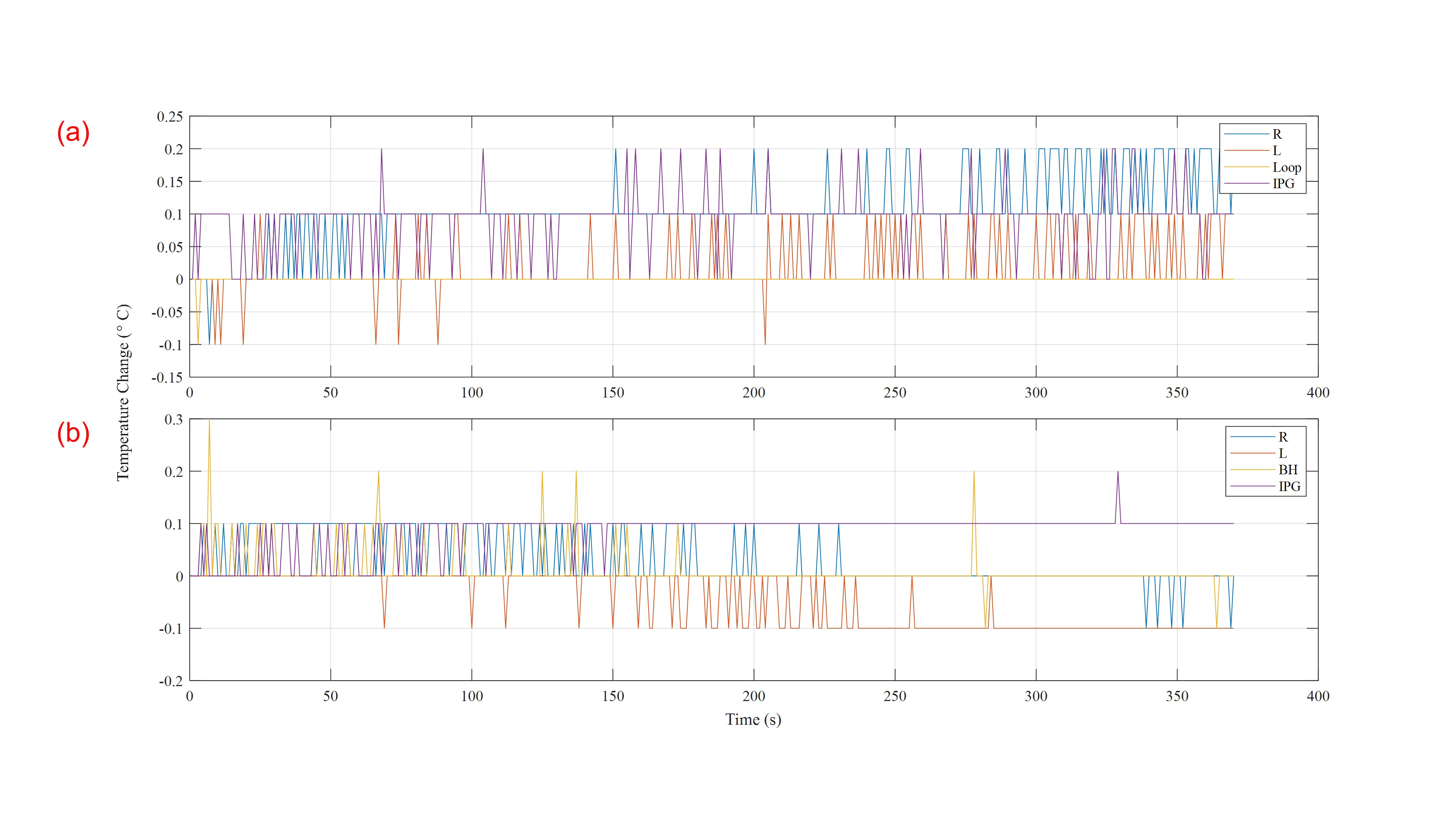
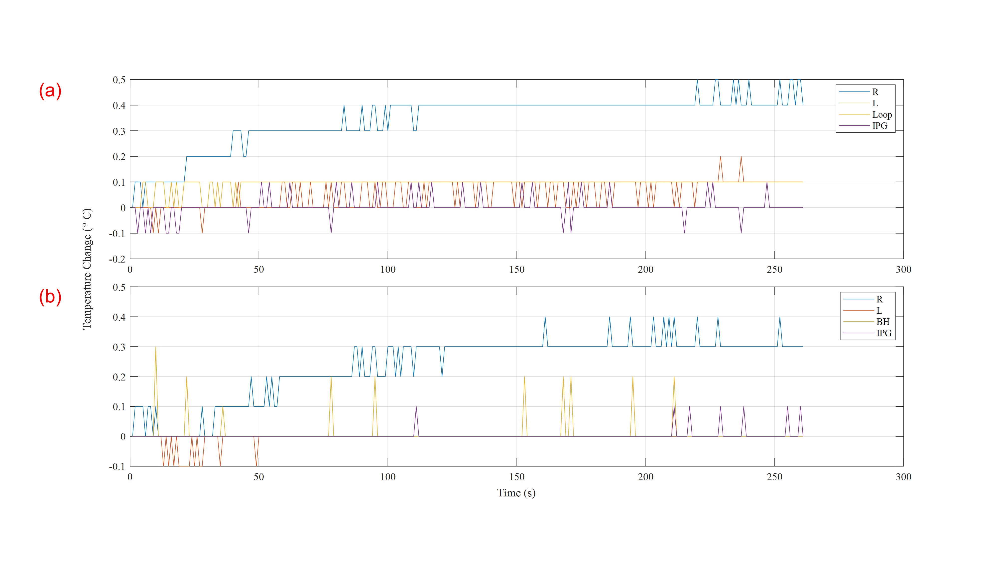
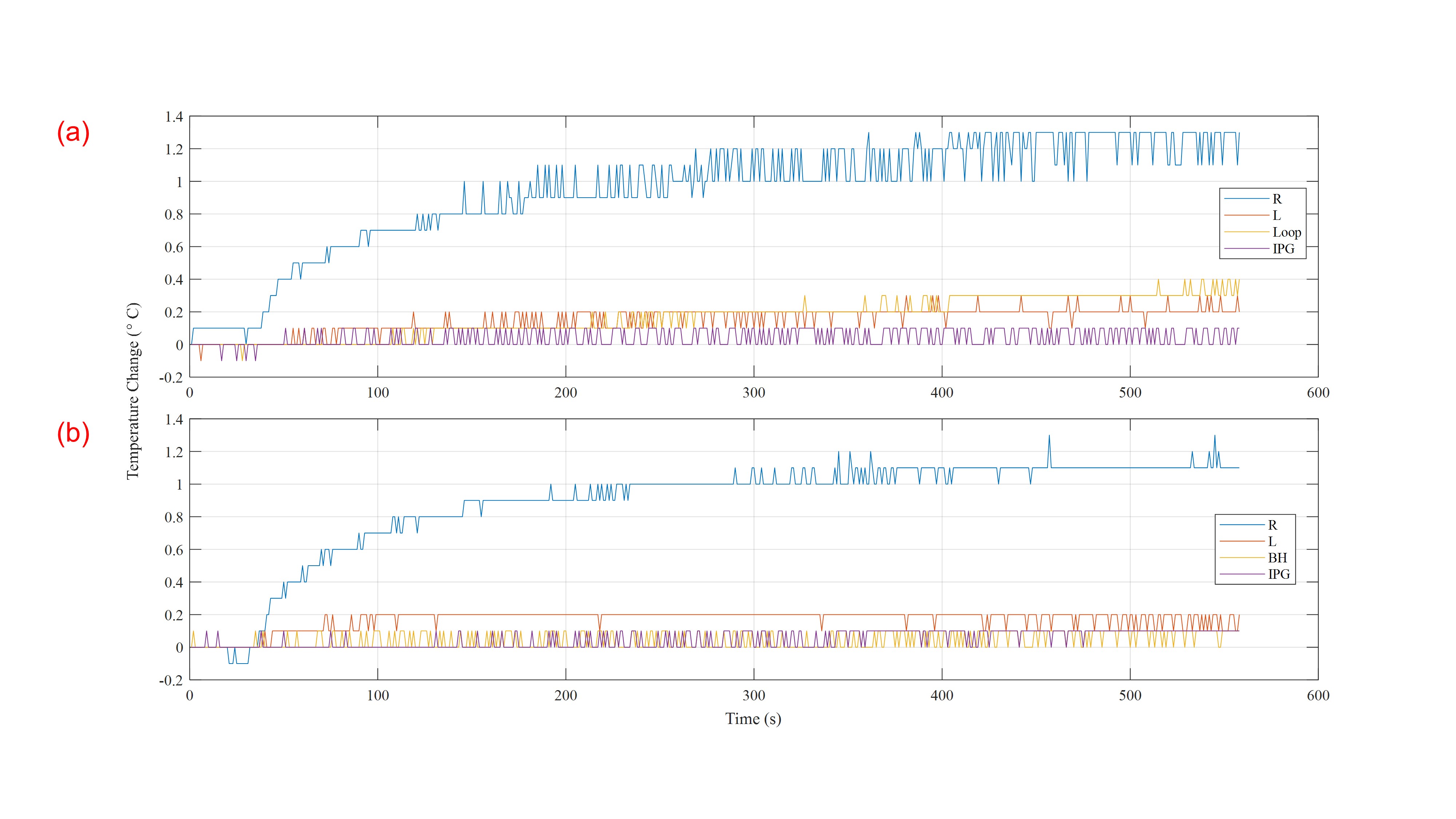
Figures 3 to 5 shows the temperature elevations during echo planar imaging (EPI), magnetization prepared rapid gradient echo (MPRAGE) imaging and turbo spin-echo (TSE) imaging, respectively. Overall, there were minimal temperature increases for EPI and MPRAGE imaging with maximum temperature changes of 0.3 ± 0.2⁰C and 0.5 ± 0.2⁰C, respectively; whereas TSE imaging reached a maximum temperature elevation of 1.3 ± 0.2⁰C for the DBS lead trajectories tested. The latter result exceeded the current imaging guidelines of +1.0⁰C for 3 T MR-conditional imaging6. In general, the RF heating effects along the DBS device were consistent for the RF pulse sequences tested over both imaging sessions and were concentrated at the DBS electrode tip implanted in the right hemisphere.Discussion and Conclusion
The preliminary RF heating results for the MR-conditional DBS device tested indicated that high SAR pulse sequences (exemplified by spin-echo imaging) remain a concern and adhering to the manufacturer’s safety guidelines remains advisable for 3 T MRI. The DBS device remained off for this study, which is the typical recommendation at our institutions. However, the manufacturer (Medtronic) recommends operating the device in “MRI mode”6. Future work will be required to investigate this mode, along with other configurations and product models. The experimental results also showed that temperature elevations in a bilateral lead setup were concentrated to a single lead. This result is consistent with previous experiments at our institution using other DBS devices1. Furthermore, the DBS electrode tips remained most susceptible to RF heating, but one secondary location showed a small temperature elevation (loop trajectory, highest applied RF power, Figure 5). The elevation was below the present safety guidelines, but further evaluation will be necessary as the present work only tested two of very many possible DBS lead trajectories. Lastly, the presented results cannot be generalized to all MRI systems – such that similar surgical procedures and experiments may result in different MRI safety outcomes.Acknowledgements
No acknowledgement found.References
[1] Davidson et al., “Three-Tesla Magnetic Resonance Imaging of Patients with Deep Brain Stimulators: Results from a Phantom Study and a Pilot Study in Patients.” Neurosurgery 2020.
[2] McElcheran et al., Parallel radiofrequency transmission at 3 Tesla to improve safety in bilateral implanted wires in a heterogeneous model. Magn. Reson. Med. 2017.
[3] Golestanirad et al., Local SAR near deep brain stimulation (DBS) electrodes at 64 and 127 MHz: A simulation study of the effect of extracranial loops. Magn. Reson. Med. 2017.
[4] Medtronic Inc., PERCEPT™ PC NEUROSTIMULATOR. https://www.medtronic.com/ca-en/healthcare-professionals/products/neurological/deep-brain-stimulation-systems/percept-pc.html 2020.
[5] Yang et al., “Technical note: an anthropomorphic phantom with implanted neurostimulator for investigation of MRI safety.” Med Phys. 2020.
[6] Medtronic Inc., MRI guidelines for Medtronic deep brain stimulation systems. 2020. https://manuals.medtronic.com/content/dam/emanuals/neuro/M929535A063A_view_d1590591026928.pdf
Figures