2558
MR signal conditioning for an electro-optic conversion with a polarization state modulator1Univ. Lyon, INSA-Lyon, Université Lyon 1, UJM-Saint Etienne, CNRS, Inserm, CREATIS, UMR 5220, U1206, Villeurbanne, France, 2Université de Savoie, IMEP-LAHC, UMR 5130, Le Bourget-du-Lac, France, 3KAPTEOS, Sainte-Hélène-du-Lac, France, 4Institut FEMTO-ST, UMR CNRS 6174, Université Bourgogne Franche-Comté, Besançon, France
Synopsis
The coaxial cables connecting coils to the MRI are subject to many unwanted interactions with RF pulses and with patients’ tissues. Currents flowing on the shielding of the cable can lead to local SAR increase and RF-induced burns. Despite their limitations and the amount of effort to discard them, there is still no satisfying alternative. One of the issue for competing technologies is to safely provide on coil power supply without cables inside the MRI. In this work, we propose to evaluate the feasibility of passive optical conversion and transmission of the signal to the MRI console.
Introduction
During an MRI examination, one of the main safety concern is related to the specific absorption rate (SAR)1. It represents the amount of energy absorbed per unit of mass by the tissues during the radiofrequency (RF) magnetic field B1 emission. The average value can be estimated in volumes of homogenous medium, but local rises can occur and lead to unacceptable increase of temperature (> 1 °C). One of the risks that is difficult to predict is the interaction between the RF field and the coaxial cable of the receive coil. Currents flowing on the shielding of the cable can induce high electric field close to the patient’s body, and it is highly geometric dependant2. The elements added to reduce this phenomenon (cable traps) are voluminous or difficult to miniaturize and heavy, which is troublesome for some applications such as endoluminal coils. Several attempts have been made to replace galvanic cables. One strategy is to transmit the signal wirelessly3. This can be done either using Wi-Fi or infrared optics, but the emitter has to be supplied (by a nonmagnetic battery for example). Another option is to use optical fibers for transmission, as fibers do not interact with B1 field. Despite all the efforts to supress coaxial cable, no solution has been yet widely implemented. We believe that the main reason is the power supply, which creates other sources of concern4. Our approach is to evaluate making use of passive elements, to propose a safe optical transmission of the signal acquired.Methods
The acquisitions are performed on a preclinical 7T MRI (Bruker, Germany), the resonance frequency is 300.13 MHz. We convert the signal received from a 23 mm inner diameter quadrature volume coil (Rapidbiomed, Germany). The phantom consists in a 15 mm diameter tube placed inside the volume coil filled with saline solution (5 g/l) and NiSo4 (1.25 g/l). The output of the coil is connected to the electro optic (EO) modulator. This is the element converting the useful electrical signal into an optical one by modulating a laser beam passing through it. It is based on a crystal whose refractive indexes are linearly modified according to the applied E field (Pockel’s effect)5. We used two modulators in this study, a commercial amplitude modulator (LN82S-FC, Thorlabs, Germany) and a custom polarization state modulator (PSM) realized by FemtoST lab (France). The PSM has lower sensitivity but does not require a bias voltage and is completely passive. The modulators are connected to an optoelectric unit (eosense, Kapteos, France) including both a laser source, and the photodiode converting the beam in an electric signal sent to the MRI console (figure 1). To evaluate the requirements of this technique, we evaluate the performance of the optical transmission chain, by changing the amplitude of the signal sent to the EO modulator. To do so, we use RF amplifiers (Minicircuit, USA), to reach 40 dB of gain with 10 dB step (Noise figure = 0.9 dB). The optical power provided by eoSense is also swept to find the optimal working point, because both the signal amplitude and the noise are linked to the optical power. The Laser has four power calibers, from 3 to 15 mW.Results
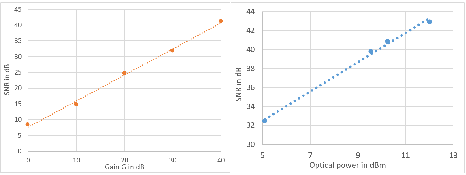
The images obtained with the commercial EO modulator are shown in fig 2. It shows that we can obtain similar quality with optical transmission as with galvanic transmission with sufficient amplification. Both modulators behaved similarly, a SNR difference of 5 dB is observed between the commercial modulator and the PSM, only due to the respective sensitivity of the modulators. The signal to noise ratio (SNR) rises along with the sensitivity of the modulation. For 40 dB amplification, we recover an equivalent SNR of image. The difference is mostly due to the several meters of coaxial cables to reach the modulator that is not on chip yet and placed far (3 meters) from the bore due to the magnetism of the packaging. The figure 3 shows that the SNR increases with the optical power.Discussion
The sources of noise involved in the optical conversion are the noise of the laser (RIN), the noise of the photodiode (shot noise) and the thermal noise. Because the RIN and the shot noise depend on the optical power and the SNR rise almost linearly with power, we can deduce that the thermal noise is the dominant factor here. This means that the noise power is comparable to that of the galvanic transmission where thermal noise is also present. Thus, the amplitude of the signal is what matters the most. To dismiss the amplifiers, we want to optimize first the modulation’s depth by designing an EO modulator with lower bandwidth and greater sensitivity6. Additionally, using more optical power to increase the SNR is another axis of improvement available.Conclusion
We demonstrate that the conversion and transmission of the NMR signal with an optical link could be achieved without degrading the images SNR. The use of specifically designed conversion elements (modulator, high power laser and photodiode) could allow transmission without amplifier, leading to a completely passive transduction between NMR signal and associated optical modulation.Acknowledgements
This work was funded by the AURA region and performed within the scope of LABEX PRIMES (ANR-11-LABX-0063). Experiments were performed on the PILoT facility, part of the France Life Imaging infrastructure (ANR-11-INBS-0006).References
1 Fiedler, Thomas M., Mark E. Ladd, et Andreas K. Bitz. « SAR Simulations & Safety ». NeuroImage 168 (mars 2018): 33 58. https://doi.org/10.1016/j.neuroimage.2017.03.035.
2 Mattei, Eugenio, Michele T. et al « Complexity of MRI Induced Heating on Metallic Leads: Experimental Measurements of 374 Configurations ». BioMedical Engineering OnLine 7, no 1 (2008): 11. https://doi.org/10.1186/1475-925X-7-11.
3 Aggarwal et al « A Millimeter-Wave Digital Link for Wireless MRI ». IEEE Transactions on Medical Imaging 36, no 2 (février 2017): 574 83. https://doi.org/10.1109/TMI.2016.2622251.
4 Nohava, Lena, Jean-Christophe Ginefri, Georges Willoquet, Elmar Laistler, et Roberta Frass-Kriegl. « Perspectives in Wireless Radio Frequency Coil Development for Magnetic Resonance Imaging ». Frontiers in Physics 8 (21 février 2020): 11. https://doi.org/10.3389/fphy.2020.00011.
5 Saniour, I, R Aydé, A L Perrier, G Gaborit, L Duvillaret, R Sablong, et O Beuf. « Active Optical-Based Detuning Circuit for Receiver Endoluminal Coil ». Biomedical Physics & Engineering Express 3, no 2 (21 février 2017): 025002. https://doi.org/10.1088/2057-1976/aa5db0.
6 R. C. Williamson, "Sensitivity–bandwidth product for electro-optic modulators," Opt. Lett. 26, 1362-1363(2001)
Figures