2557
Investigation of the Ability of Slot Element Metallization to Reduce SAR and RF Heating due to Associated Components1Electrical Engineering, Kuwait University, Abdullah Al Mubarak Al Sabah, Kuwait, 2Texas A&M University, College Station, TX, United States
Synopsis
Evidence indicates that excess RF power from coil’s associated circuitry could cause injuries to patients. Slot elements have been investigated earlier and demonstrated good potential when used for multi-channel RF coils. Here we investigate the potential of using the extended metallization of slot elements to shield stray electric field generated from RF coil associated circuitry. RF heating experiment was designed to compare the temperature of the phantom with and without using the slot’s extended metallization to shield the associated circuitry. Experimental results demonstrated an observable reduction in the phantom temperature resulting from extending the slots metallization.
Purpose
Researchers are investigating new RF coil designs and elements to mitigate challenges associated with high field MRI such as B1+ inhomogeneity and increased SAR levels [1]. The use of multi-channel RF coil represents an important approach to overcome challenges associated with the use of high field MRI [1, 2]. As the number of channels increases the number of the associated circuitry such as match and tune networks, baluns and feed lines can significantly increase around the imaging region. These circuities may generate stray electric field that could contribute to the deposited RF heat and SAR level within phantoms. Evidence produced by U.S. Food and Drug Administration (FDA) on injuries received during clinical MRI, point to excess RF power deposition as a cause for adverse effects on patients [3]. Some of these injuries were due to leads including coil’s cable and metal [3]. Modeling the coils' associated circuitry does not represent a common approach when designing array coils. Slot array has been investigated earlier and demonstrated good potential when used for multi-channel RF coils [4, 5]. Slot elements have a unique characteristic of operating as an aperture within a meatal surface. Here we investigate the potential of using the extended metallization of slot elements to shield stray electric field generated from RF coil associated circuitry.Method
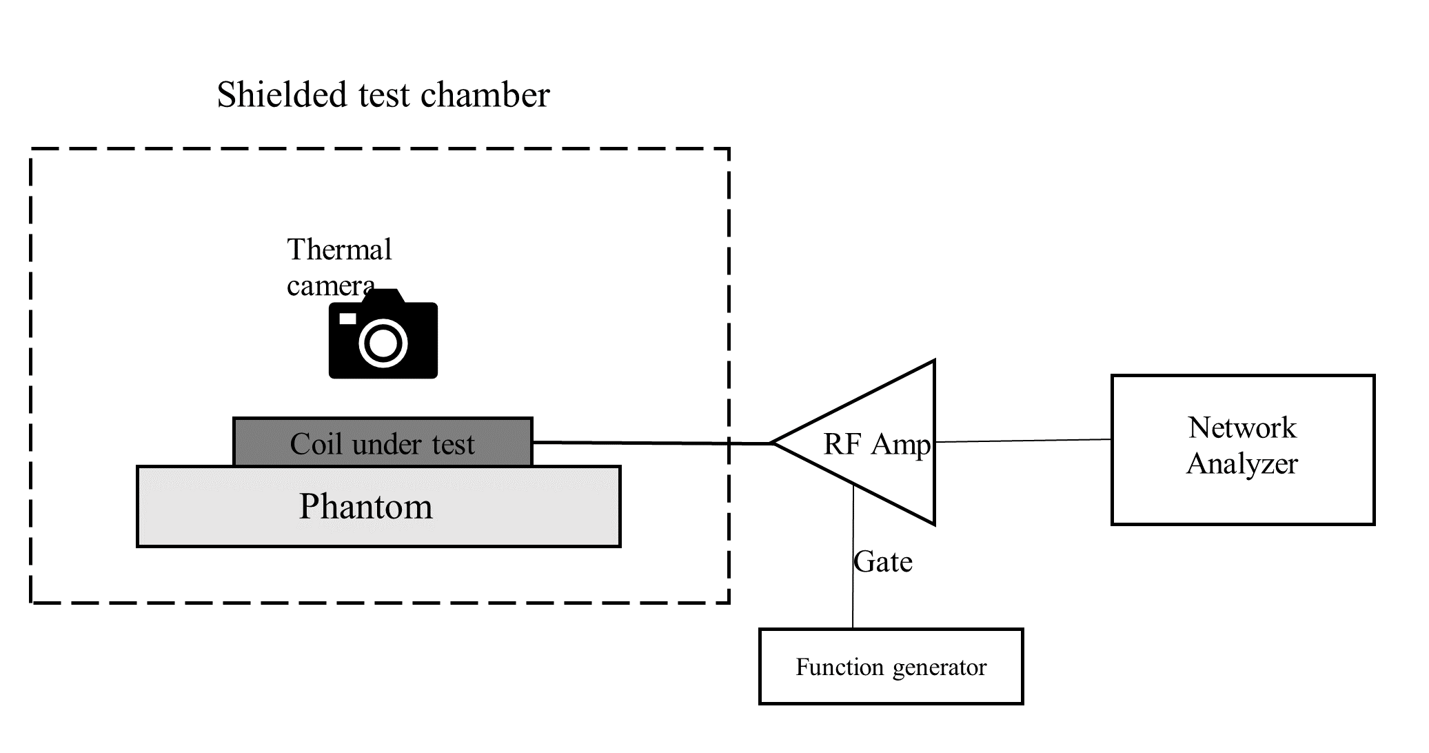
To demonstrate the anticipated reduction in RF heating withing phantoms, two bow tie dual slot modules were used. Detailed design of the dual bow tie slot modules was described earlier in [5]. The first module has an extended metallization with associated circuitry shielded behind an extended PCB (see Fig.1). For the second module the PCB was shortened to expose the circuitry.The following experimental setups were used (see Fig.2); A 200 MHz RF signal, generated from a network analyzer, represented the input drive of an RF power amplifier (AMT 3200LP, BREA, USA) as a 10 ms pulse width with a 5% duty cycle, generated from a function generator, represented the blanking input for the amplifier. The amplifier output, with a 200 W peak power (10 watt average power), was used as the input for the dual slot module to induce RF field within the phantom. The phantom, placed directly below the dual slot module, contained a 25 x 15 x 40 cm3 saline water ager-gel with a dielectric constant of 77 and conductivity of 0.6 S/m. After two minutes of excitation, we used a FLIR i7 infrared camera (FLIR Systems, USA) to measure the heat generated within the phantom directly underneath the balun and the matching network. The two minutes of excitation was chosen to maintain the temperature and SAR linear relation [6],allowing for SAR estimation.
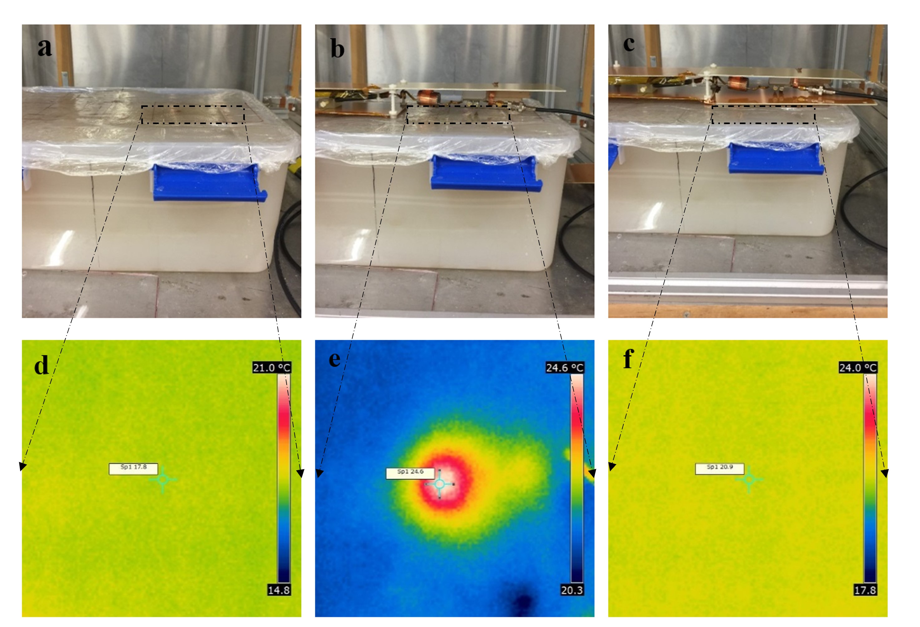
Before starting the heating experiment a reference thermal image was taken with FLIR infrared camera. The heating experiment was conducted twice under the same settings. In the first experiment, we used a dual slot module with an extended PCB to shield the balun matching and tuning network and the feed lines from the phantom. In the second experiment, we used a dual slot module with the shortened PCB, exposing the balun, matching and tuning network and the feed lines to the phantom. The distance between the matching and tuning network and the phantom remained constant for experiments by using an acrylic sheet to substitute the extended PCB. Immediately after each heating experiment thermal images using FLIR infrared camera were taken underneath the (matching network). Sufficient time was permitted between the RF heating experiments to allow the phantom to cool down and a thermal image was taken to assure that the reference temperature was the same for both experiments.
Finally, using the acquired thermal images the highest recorded temperature in each image was used to estimate the corresponding SAR value as described in the following formula [6];
SAR = Cphantom ΔT/Δt
where Cphantom represents the heat capacity of the ager-gel phantom. The heat capacity used for SAR analysis equals 4200 J/Kg·oC, as given by [7].
Results
Thermal images recorded the highest temperature under the coil’s circuitry as 21 oC and 24.6 oC for the module with extended PCB and the module with the shortened PCB, respectively (see Fig. 3).The reference temperature for the phantom was recorded as 17.8 oC. These measurements map to 112 W/kg and 238 W/kg, SAR values respectively [7]. Because the RF heating experiment was intentionally designed to heat the associated coil circuitry, the amount of the applied power is much higher than the average applied power in MRI experiments. Thus, the resulting SAR values are higher than the reported levels from MRI experiments.Discussion
Experimental results demonstrated an observable reduction in the phantom temperature resulting from extending the slots metallization. Specifically, a 3.6 oC reduction in phantom temperature due to the presence of the extended metallization of the slot module. This reduction in phantom’s temperature led a corresponding reduction in the estimated SAR value by more than 50%. The ability to reduce the RF heat and SAR generated from the coils' associated electronic components reflects an important advantage when using slot modules for high field MRI.Acknowledgements
No acknowledgement found.References
1. Hernandez, D. and K.-N. Kim, A Review on the RF Coil Designs and Trends for Ultra High Field Magnetic Resonance Imaging. Investigative Magnetic Resonance Imaging, 2020. 24(3): p. 95-122.2. Karamat, M.I., S. Darvish-Molla, and A. Santos-Diaz, Opportunities and challenges of 7 tesla magnetic resonance imaging: a review. Critical Reviews™ in Biomedical Engineering, 2016. 44(1-2).
3. Stralka, J.P. and P.A. Bottomley, A prototype RF dosimeter for independent measurement of the average specific absorption rate (SAR) during MRI. Journal of Magnetic Resonance Imaging: An Official Journal of the International Society for Magnetic Resonance in Medicine, 2007. 26(5): p. 1296-1302.
4. Alon, L., et al., Transverse slot antennas for high field MRI. Magnetic resonance in medicine, 2018. 80(3): p. 1233-1242.
5. Dheyaa Alkandari, N.H., Chung-Huan Huang, Jiaming Cui, and Steven M Wright. A 16 Element Bow-Tie Slot Array Coil for Parallel Transmit MRI/MRS. in ismrm. 2017.
6. Oh, S., et al., Experimental and numerical assessment of MRI‐induced temperature change and SAR distributions in phantoms and in vivo. Magnetic Resonance in Medicine: An Official Journal of the International Society for Magnetic Resonance in Medicine, 2010. 63(1): p. 218-223.
7. Oh, S. and C.M. Collins. Experimental Temperature and Specific Absorption Rate Mapping Using MRI in a Transmit-receive Head Coil at 3.0 T. in Progress In Electromagnetics Research Symposium Abstracts. 2008.
Figures
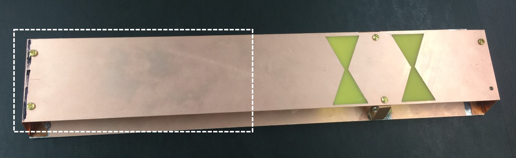
Fig. 1. Dual slot bow tie module enclosing feed lines, balun, and match and tune network. The removed part of the front PCB for the shortened metallization module is marked with the white border. Underneath this marked part of the PCB is where the feed lines, balun, and match and tune network are located.