2549
An extended version of the restricted SAR protocol allowing safe in vivo testing of RF coils in an unconditional and flexible way
Natalia Dudysheva1,2, Alexis Amadon1, Alexandre Vignaud1, Redha Abdeddaim3, and Franck Mauconduit1
1CEA, NeuroSpin, Paris-Saclay University, CNRS, Gif-sur-Yvette, France, 2Multiwave Imaging, Marseille, France, 3Fresnel Institute, Aix-Marseille University, CNRS, Marseille, France
1CEA, NeuroSpin, Paris-Saclay University, CNRS, Gif-sur-Yvette, France, 2Multiwave Imaging, Marseille, France, 3Fresnel Institute, Aix-Marseille University, CNRS, Marseille, France
Synopsis
This work promotes the RF coil elaboration facilitating its in-vivo testing phase. To exclude patient risk, in-vivo studies with each new coil configuration require prior SAR verifications and commission approval lengthening the design process. The so-called “Restricted SAR” (rS) protocol offers a solution to safely use homemade coils in vivo at any development stage without prior validation. This protocol constrains transmitted RF power and automatically respects the SAR safety limits, whatever the SAR distribution. Here, we propose the extended rS protocol with flexible sequence parametrization. This adjustability offers better B0 mapping coverage, optimal B1+-map estimation, and higher spatial image resolutions.
Introduction
The ultra-high field MRI poses a huge interest for clinical and research studies and demands new instrumentation solutions, including coil design1,2. The development of a new antenna involves in-vivo tests to verify the construction correctness and thus must ensure patient safety. One of the crucial requirements is a low specific absorption rate preventing body overheating. The demand for global and local SAR restrictions becomes more exigent for higher fields where elevated RF energy and strongly inhomogeneous SAR take place2,3. Since the SAR distribution depends on coil configuration, in-vivo tests need numerous preliminary SAR simulations and checks on phantoms and human-head models with subsequent consideration by local (IRB) and, in some countries, national ethics commissions. Human studies can reveal the need to redesign the coil and prompt a new verification cycle for refined geometry. Thus, this process is highly resource- and time-consuming; it deprives time for experimentation and remodeling and slows down the coil development stage. To accelerate the design process, the so-called “restricted SAR” (rS) protocol has been proposed4. This work extends the previous version enabling the parameter variation and new sequence features. The new rS protocol offers better B0 mapping coverage, optimal B1+-map estimation, and compatible MR image contrasts at higher spatial resolutions.Methods
The rS protocol constraints rely on energy conservation and guarantee the respect of the IEC guidelines for global and local (10-gram averaged) SAR values5 by limiting the transmitted RF power. Even in a hypothetical worst-case situation where the total input power is absorbed by a single 10-gram piece of biological tissue, local and global SARs remain below regulatory limits. Under these conditions, for head studies, the maximum power supply averaged over 6 minutes becomes 0.1 W. The short-term limit for 10 seconds is 0.2 W. The protocol calculates the energy in the corresponding time interval for given sequence settings and compares it to the limit. The user can change the parameters keeping the output power within the safe range. The calculation of the previous protocol limits assumes an uneducated user, which will possibly apply the maximum available reference voltage. This hypothesis freezes numerous sequence parameters such as TR, flip angle, and interleaved multi-slice mode limiting the sequence capabilities. Now the sequences automatically adjust the range of available parameters depending on the required reference voltage, similar to the usual unrestricted mode.The extended rS protocol was implemented for three sequence source codes (Fig. 1): gradient recalled echo (GRE), used for localizer, B0 shimming and T2*-weighted images, XFL providing B1+-map, and echo-planar imaging (EPI). Sequence testing was performed on a Magnetom 7T MRI scanner (Siemens Healthineers, Erlangen, Germany) with a SC72 whole-body gradient (maximal amplitude 100 mT/m and slewrate 200 T/m/s) using Head Coil 1Tx/32Rx (Nova Medical, Willington, USA) in single-channel receive mode. After phantom verification, we tested the old and new protocols on a healthy volunteer in accordance with local IRB rules. The new rS protocol used the most optimal available parameters for each sequence (Fig. 2). For a more accurate B1+-map analysis with the new protocol, the XFL parameters were tuned to minimize the uncertainty of the targeted flip angle. The noise-induced FA error was estimated for different α/β (see Fig. 1) ratios6 considering the SNR dependence on the excitation angle β and the proportionality of the α and β distributions (Fig. 3). Actual Flip angle Imaging (AFI) applied in the non-restricted mode provided the gold-standard B1+-map.
Results
Both protocols were used to obtain a localizer, a B0-map, and a B1+ distribution map. The FA uncertainty analysis gave the optimal saturation and excitation XFL flip angles of α=60°-80° and β=4°-7°. The resulting FA distributions for XFL were compared with the AFI map to evaluate their precision (Fig. 4). The new protocol version additionally provided EPI and T2*-weighted images (Fig. 5).Discussion
The extended rS protocol allows additional experimental options including both interleaved and sequential multi-slice modes for GRE and XFL, fat/water suppression, and magnetization preparation for GRE and EPI. This adjustability allows shorter TA and better image quality. In addition, the same sequence allows for different types of contrasts (e.g., rS_GRE code works for T2*-weighted imaging and B0-map). The new version yields B0-shimming with improved coverage (Fig. 5). The B1+-map comparison shows that the old version provides a biased FA and stronger sensitivity to B0 inhomogeneities due to the long rectangular saturation pulse used. The current protocol permits different pulse types including SLR, which delivers a more precise B1+-map closer to the AFI results. The appropriate parameters for a more accurate FA distribution analysis allow a better assessment of the coil transmission profile. Moreover, for experiments such as T2*-weighted imaging, the extended rS protocol enables high single-slice resolution (0.5x0.5x4.0 mm3). This image quality gives reason to think about expanding the protocol applications for other research purposes requiring severe SAR limitations.Conclusion
The rS protocol ensures the safe use of the RF coil prototype in vivo without complex prior validation, which significantly saves time and resources. The extended protocol version offers more accurate antenna characterization and new experimental opportunities. This simplicity and adjustability push forward the RF coil development at ultra-high field.Acknowledgements
This study has received funding from the European Union's Horizon 2020 research and innovation program under grant agreement No 952106 (M-ONE project) and from Leducq Foundation (Large Equipement ERPT program, NEUROVASC7T project). We also thank Bruno Pinho Meneses for his idea of an extended rS protocol.References
- A.G. van der Kolka, Hendrikse J. et al. Clinical applications of 7 T MRI in the brain. European Journal of Radiology, 2013; 82 708–718.
- Karamat M. I., Darvish-Molla S. & Santos-Diaz A. Opportunities and Challenges of 7 Tesla Magnetic Resonance Imaging: A Review. Crit Rev Biomed Eng, 2016; 4 4(1-2):73-89.
- Hoff M. N., McKinney A. et al. Safety Considerations of 7-T MRI in Clinical Practice. Radiology, 2019 Sep; 292(3):509-518.
- Vignaud A., Mauconduit F. et al. Fast and unconditionally safe in vivo MR head protocol for home-made coil prototype assessment at 7T. Journal of Physics: Conference Series, IOP Publishing, 2018; 1092, pp.012159.
- International Electrotechnical Commission. IEC 60601-2-33:2010: Medical Electrical Equipment - Part 2-33: Particular Requirements for the Basic Safety and Essential Performance of Magnetic Resonance Equipment for Medical Diagnosis. 3rd ed. with amendments. International Electrotechnical Commission; 2015. (accessed September 2020).
- Pohmann R. and Scheffler K. A theoretical and experimental comparison of different techniques for B1 mapping at very high fields. NMR Biomed, 2013; 26: 265–275.
Figures
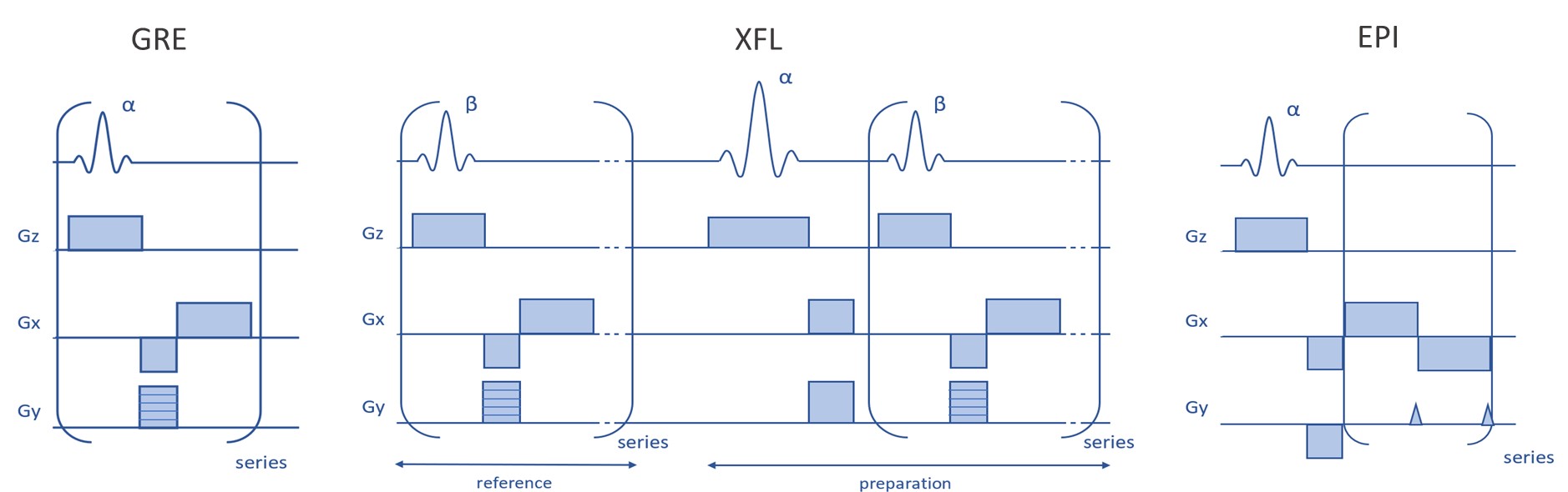
Fig.1. Simplified schemes of the sequences used for
the protocol implementation.
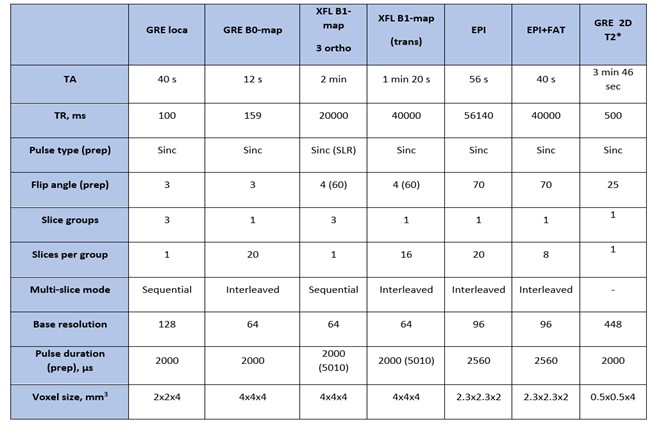
Fig. 2. Description of the new protocol. During
protocol launch, SAR values were monitored. The resulting SAR display on the MR
scanner interface was always < 1% of the IEC limit.
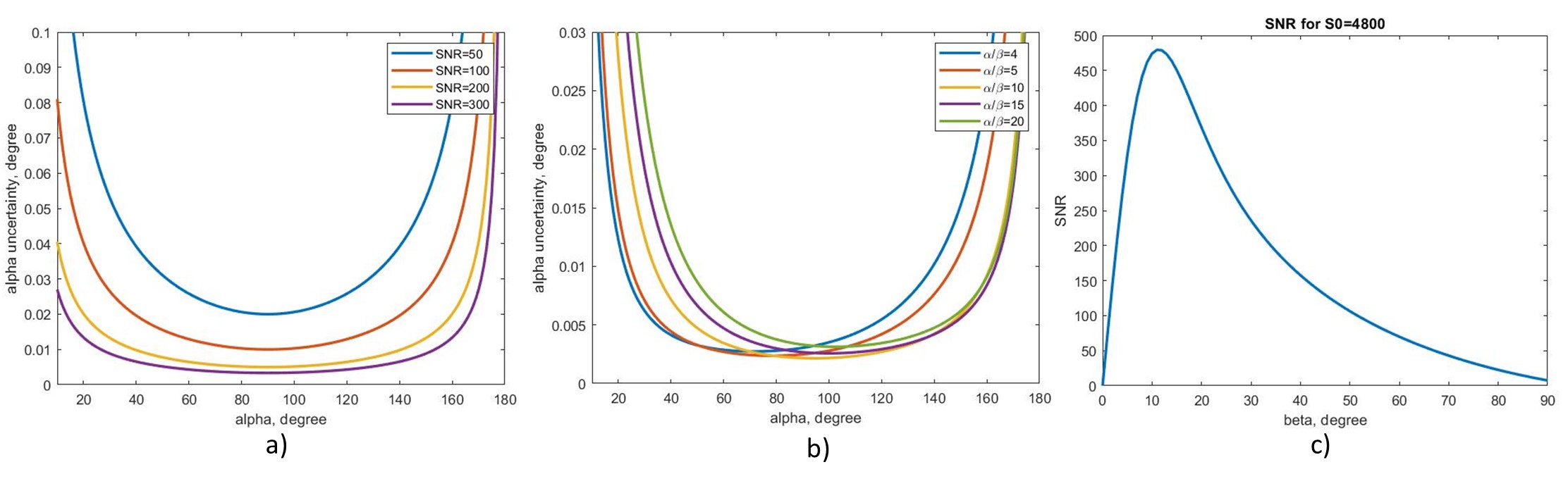
Fig. 3. Uncertainty of the preparation FA
depending on the SNR (a) or the α/β value (b). (c) represents SNR versus beta
for the intrinsic SNR S0=4800; this S0 value provides the same SNR as in the
acquired reference images.
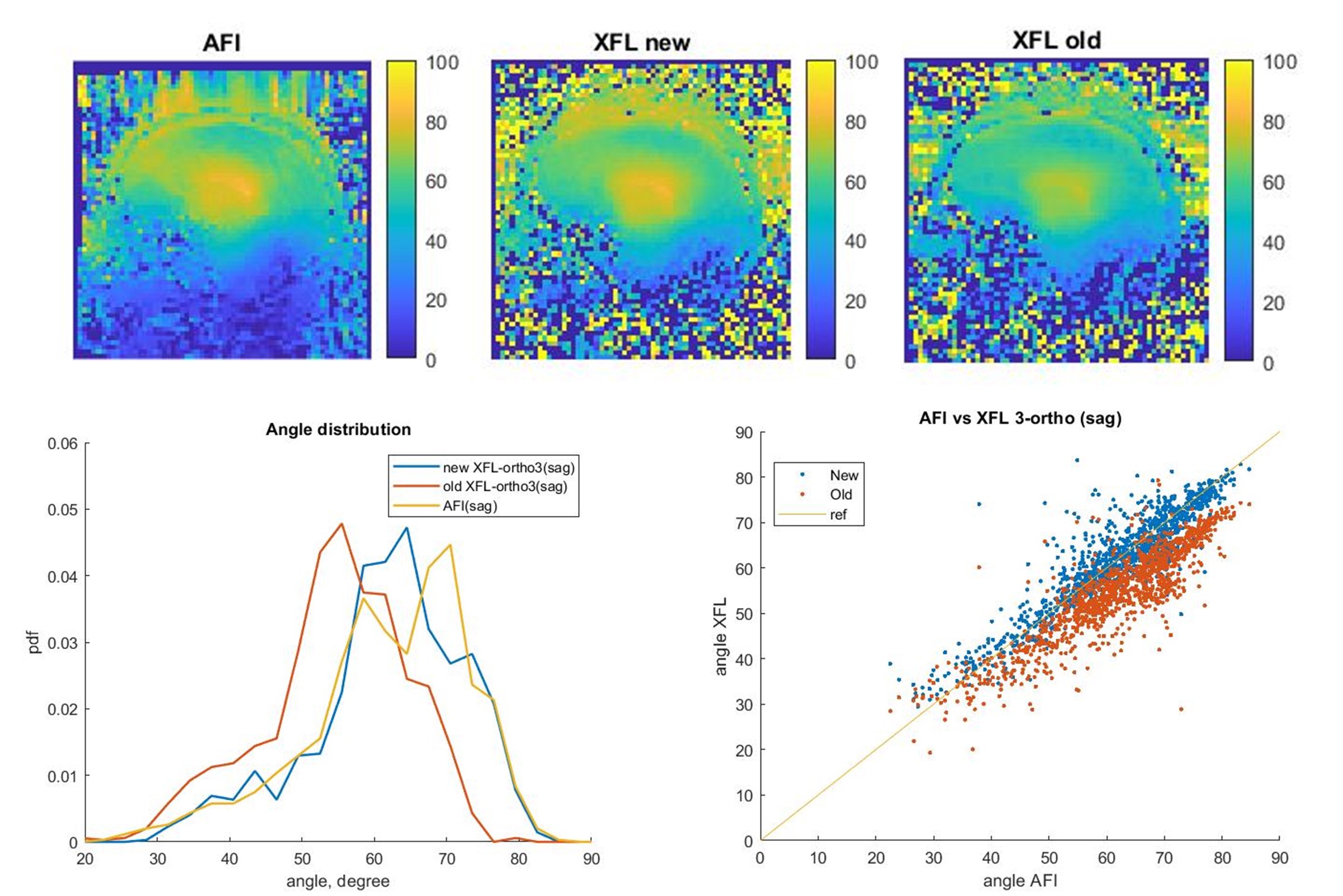
Fig. 4. B1+-map comparison for AFI and old and new versions of the restricted XFL.
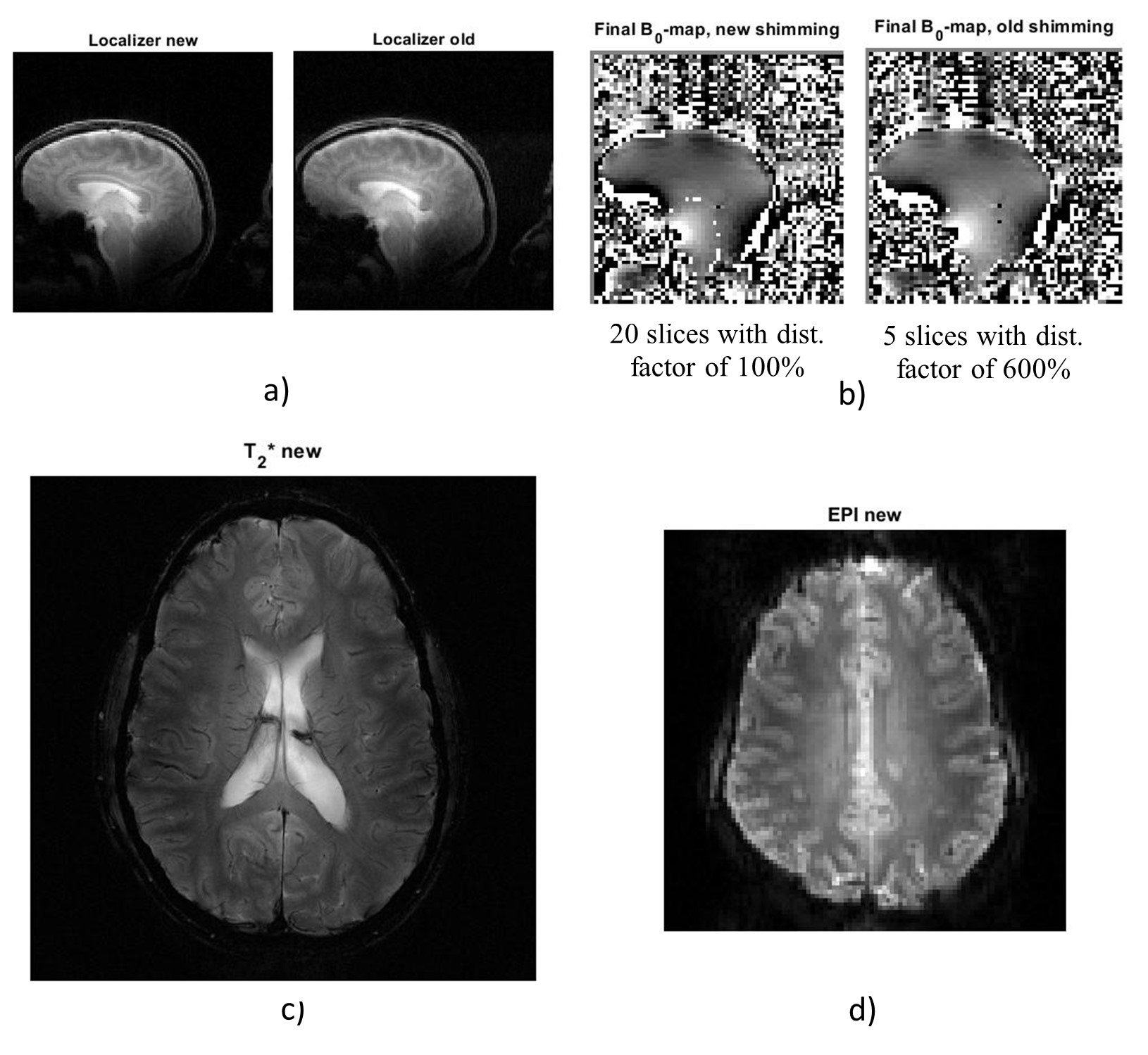
Fig. 5. Acquired images: a) Localizer for new and old protocols, b) B0-maps for both protocols after shimming, c) T2*-weighted image for the new protocol and d) EPI image for the new protocol.
DOI: https://doi.org/10.58530/2022/2549