2447
Synchronizing TMS pulses for free artifact fMRI for multichannel TMS systems using the integrated whole head TMSMR 28 channel RF coil array1Martinos Center - MGH, Charlestown, MA, United States, 2Harvard Medical School, Boton, MA, United States, 3Harvard Medical School, Boston, MA, United States
Synopsis
For TMS/fMRI experiments, to acquire functional images without artifacts, general recommendations have been proposed. In order to apply TMS pulses in a multichannel Transcranial Magnetic Stimulation system integrated with the new constructed TMSMR 28- channel RF coil, we have explored the different options and artifacts that can be generated depending on when the TMS pulses are applied with respect to the sequence timing. As conclusion, we propose a method using an RF pick up loop to assure that the delivery of the TMS pulses are not close to the EPI navigators or the imaging gradients.
Introduction
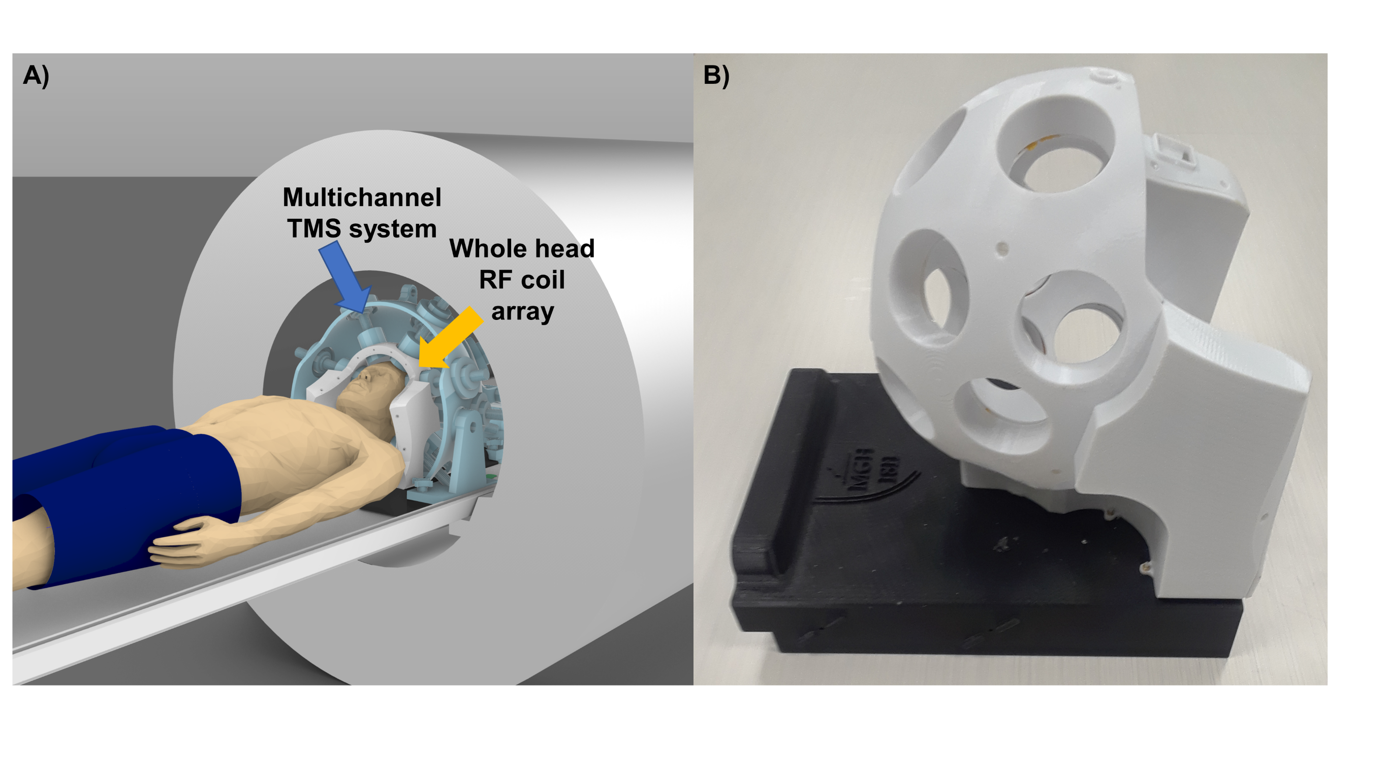
Multichannel Transcranial Magnetic Stimulation (mTMS) is an emerging technology for non-invasive stimulation of the human brain. The use of multiple TMS coils in an array configuration enables shifting the location TMS ‘hot spot’ electronically without any mechanical movement. This is achieved by computationally determining the current amplitudes to be passed to each of the coil elements to synthesize a desired target field pattern (1). Combining non-invasive stimulation techniques such as TMS with fMRI offer the unique benefits of studying the causal relationships and functional connectivity between the nodes of large-scale brain networks. In particular, the mTMS technique would be become powerful when used in conjunction with functional MRI (fMRI), since maneuvering any TMS coil inside the scanner environment either manually or robotically is rather cumbersome.We have constructed a whole head 28-channel RF coil array to be integrated with the first 3-axis TMS (2) multichannel system (see Figure1). The basic combination of single-channel TMS and fMRI has been demonstrated (3) and proven to be safe (4). Artifacts produced during imaging were carefully studied somewhere else (5,6) and general recommendations were presented. To quantitatively understand the origin of the artifacts, we propose a simple method to measure the relative timing of the MRI and TMS pulses. We conducted an explorative experiment to analyze the effects of the TMS timing with respect to the imaging sequence to be applied for our novel multichannel 3-axis TMS system integrated with a whole head RF coil array.Methods
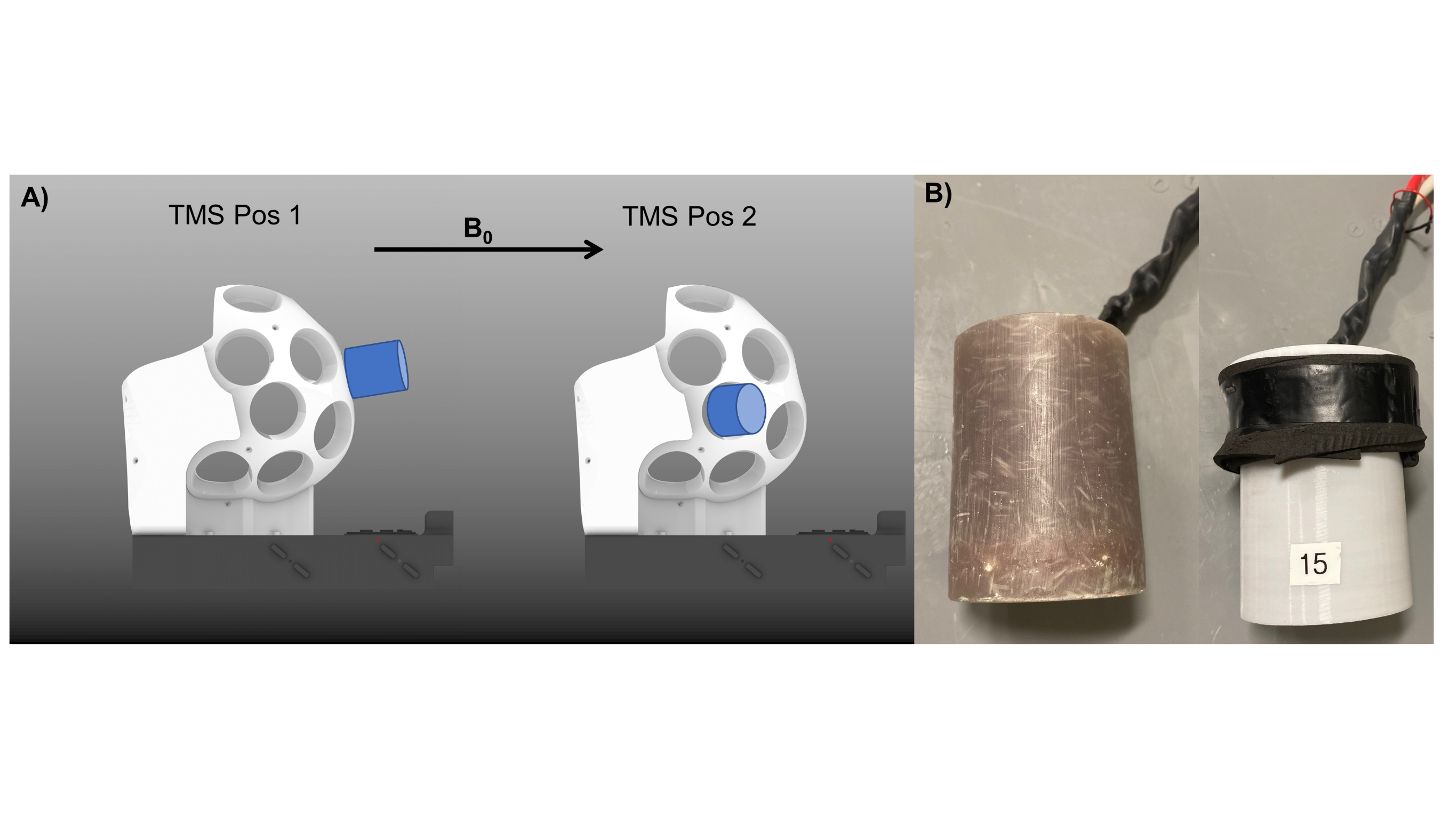
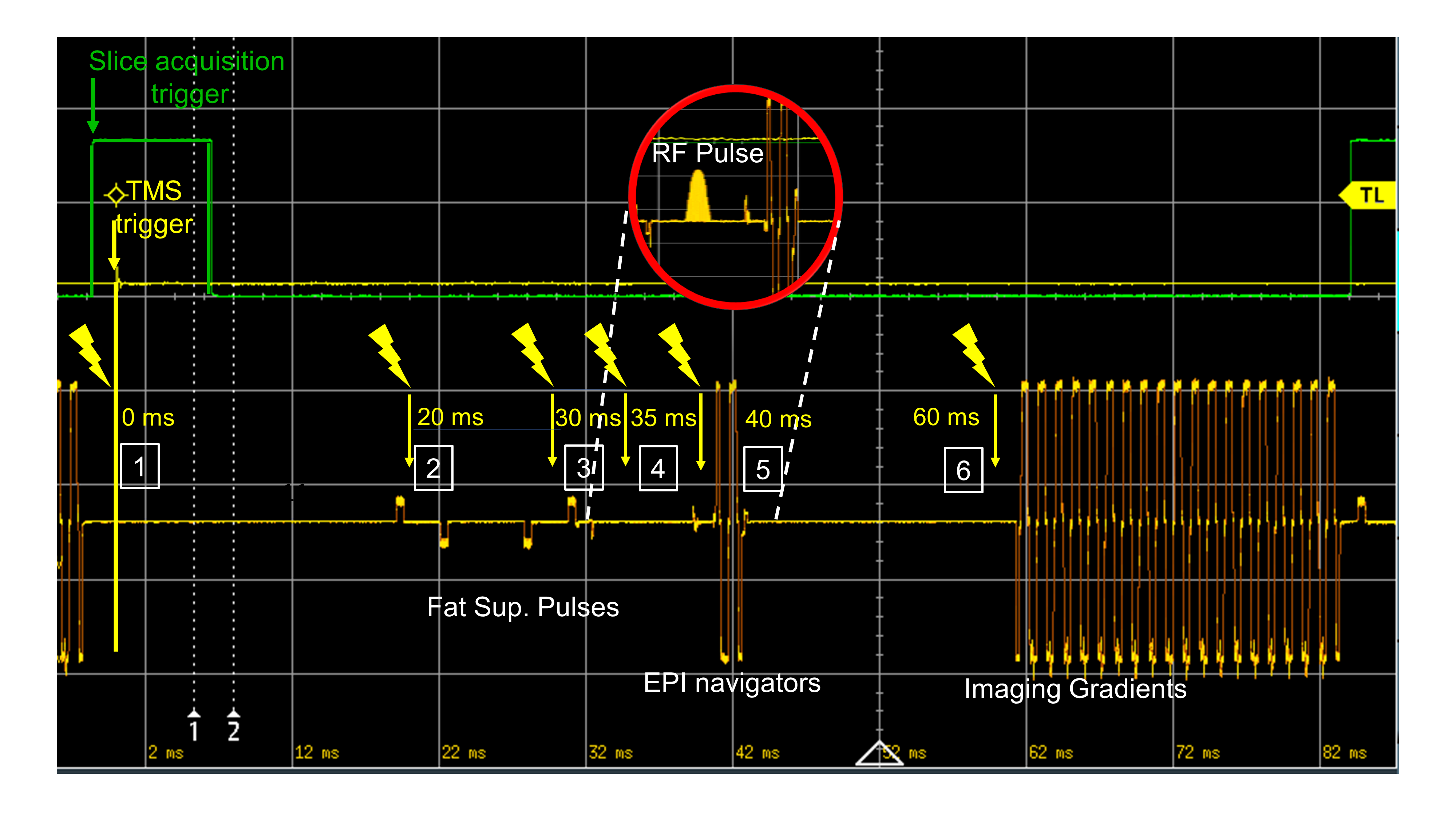
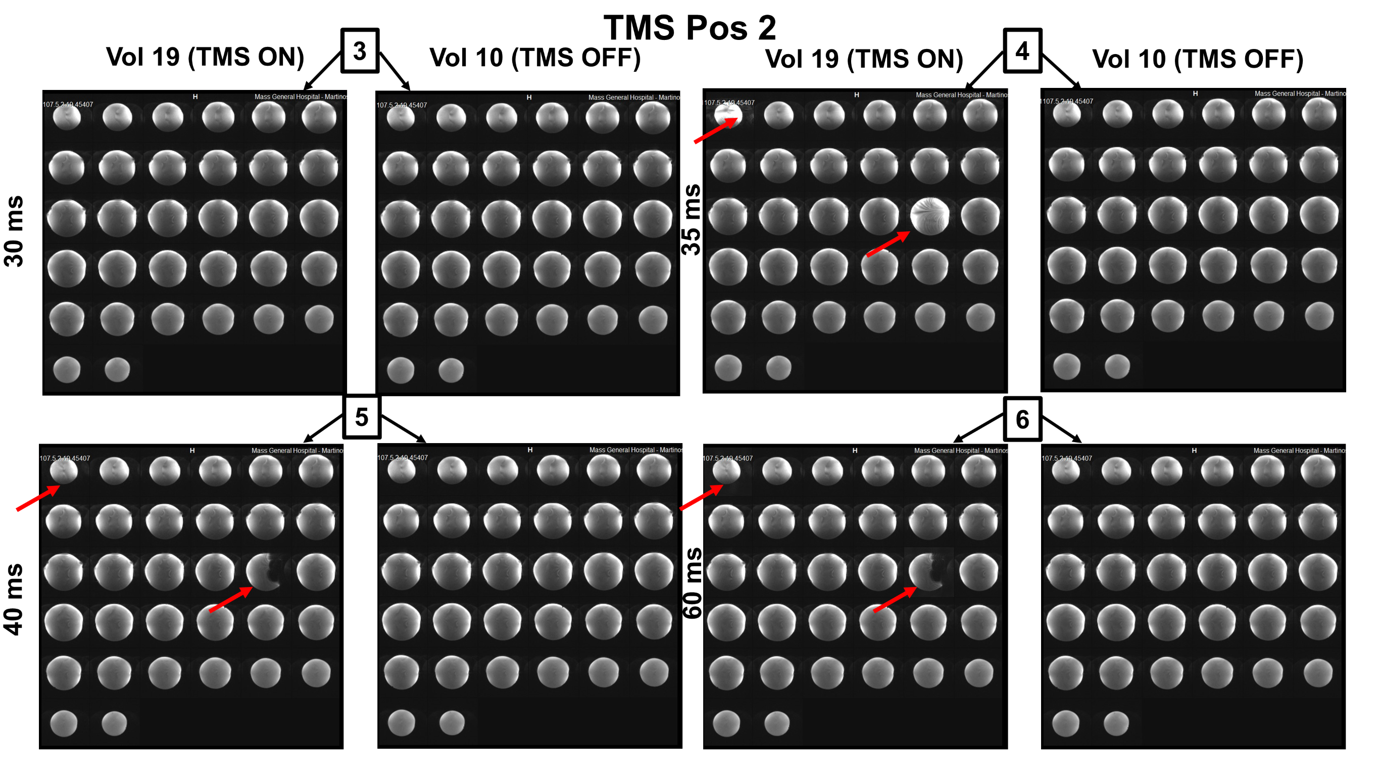
Using our recently developed whole head TMSMR 28-channel RF coil array (see Figure1B), we applied TMS pulses during the acquisition of functional images using simultaneous multi-slice EPI (7) of an spherical phantom (32 slices, grappa 2,TE=35ms, TR 1130ms, 2.5mm in-plane resolution, SL=2mm, MA88x88, FA90°) using a z-coil element of the 3-axis system that was potted in epoxy (2)(see Figure2B). The z-coil element was placed in 2 different positions in our TMSMR 28-channel RF coil (see Figure2A). The two different positions were selected to investigate the effects of torque and vibrations on the TMS coil (positions 1 and 2 present low and high torque conditions, respectively). The TMS pulses were applied in 5 blocks (1 pulse per volume in a pre-defined slice acquisition window) following a 10-volume period with no TMS pulses. The intensity of the stimulator was chosen to be 15%. An additional z-coil element was placed close to RF coil in the center of the bore to act as a magnetic field pick up loop to acquire detailed sequence timing data. The TMS pulse triggering was synchronized with the slice timing triggers produced by the scanner and was implemented using Presentation software (Neurobehavioural Systems, Berkeley, CA,US). The TMS pulse were applied with various delays (0, 20ms, 30ms, 35ms, 40ms and 60ms) for both positions. To record the trigger signals and the signal produced in the z-coil used as a pickup loop, we used a digital oscilloscope (RTB2004, Rhode&Schwarz).Results
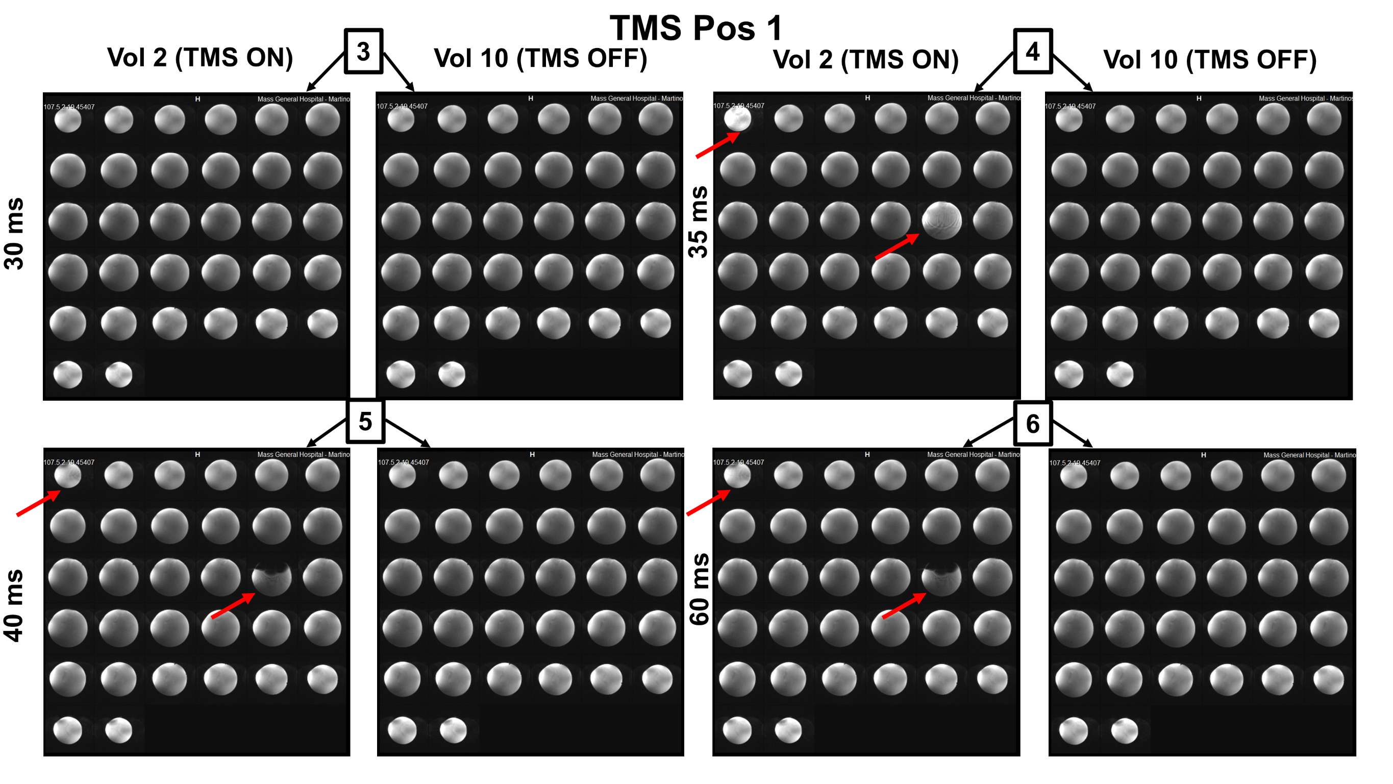
Figure3 shows the oscilloscope traces of the captured signals. The green channel is the TTL pulse produced by the sequence for every slice acquisition, The acquisition below in yellow shows the signal captured by our external z-probe (not the one placed inside the RF coil for delivering magnetic pulses). This provides specific information of the MRI pulse sequence any given time. The TMS pulses were given in the 6 conditions defined above, which are represented in Figure3 with a lighting symbol on the exact time when they occurred. Pulses given with the delays of 0ms, 20ms, and 30ms did not have any visible consequence on the image quality. However, different artifacts were observed when the TMS pulses were delivered exactly at 35ms (at the same time as the RF excitation pulse), or at 40ms (affecting the EPI navigators) and at 60ms (affecting the imaging gradients). Figure4 and Figure5 presents the observed artifacts for each of the studied positions (Position 1 and 2, respectively). The artifacts produced when the delay was 40ms or 60ms are very similar, cutting out a part of the phantom. The artifact that occurs when the delay is exactly 35ms is similar for both positions and shows ringing effects on the phantom. The artifacts affect always the first and the 17th slice due to the multiband sequence (shown in red in the figures).Discussion
The results obtained in this study show that general recommendations to avoid artifacts on TMS-fMRI experiments should be avoided unless a relatively long ‘pause’ between EPI volumes can be introduced (6). A pick-up loop or probe should be used to measure of the sequence timing to determine appropriate times to deliver the TMS pluses in continuous fast fMRI acquisition scenarios. Even though the TMS pulses are very short (~300micros), they have a strong effect especially when placed closed to the EPI navigators and Imaging gradients. We did not observe any influence of the higher torque on Position 2, indicating that the explanation of artifacts being produced by eddy currents induced to the coil due to vibration was not supported by the data. However, further investigations with various stimulator current intensities should be done to elucidate the various TMS-induced artifacts and their origins.Acknowledgements
This work was funded by NIH R00EB015445, R01MH111829, NIH R00EB021349 and the Rappaport Foundation.References
(1) Ruohonen J and Ilmoniemi R. Medical and Biological Engineering and Computing, Vol. 36 p297-301,1998
(2) Navarro de Lara et al., NI, 224 117355, 2021
(3) Bohning et al.,Invest Radiol,33(6):336-340,1998
(4) Navarro de Lara et al., MRM, 84(2), p:1061-1075, 2020
(5) Bestmann et al. JMRI, 17:309-316 (2003)
(6) Navarro de Lara et al., MRM 74:1492-1501 (2015)
(7) Setsompot et al., MRM 67 (5) 1210-1224, 2012
Figures