2431
Reusable 3D Printed Ex-vivo Brain Enclosure and Two-Piece Cutting Guide for Axial and Coronal MRI Registration with Gross Anatomy Photographs1University of Pittsburgh, Pittsburgh, PA, United States
Synopsis
A 3D printed re-usable box enclosure and two-piece cutting guide were developed to produce high quality 7T MR images that can be easily registered to gross anatomy and histology. Cuts can be made parallel or at multiple angles at 5mm intervals in both the axial and coronal orientations.
Introduction
7 Tesla (T) magnetic resonance imaging (MRI) of Ex-vivo brains can be paired with gross anatomy to better understand neuroanatomy. Ex-vivo imaging offers advantages including extending sequence time to produce higher resolution and SNR in conjunction with zero motion artifacts and cardiovascular movement. Post-mortem MRI, however, has associated challenges including field inhomogeneity at ultrahigh fields, and intricate registration mechanisms due to tissue deformation and brain fixation (1-5). A custom anatomically conforming 3D printed cutting guide has been used by others in attempt to minimize tissue deformation and aid in registration for individual brains (1-4). This cost- and time-consuming process produces the desired results but is not reusable and requires a custom manufactured cutting guide for each brain. We propose the use of a reusable, 3D printed enclosure with separable two-piece cutting guides, filled with agarose to fixate a range of brain sizes, mitigated B1 inhomogeneities, cutting freedom and precision for pathologists, as well as fast and accurate registration.Methods
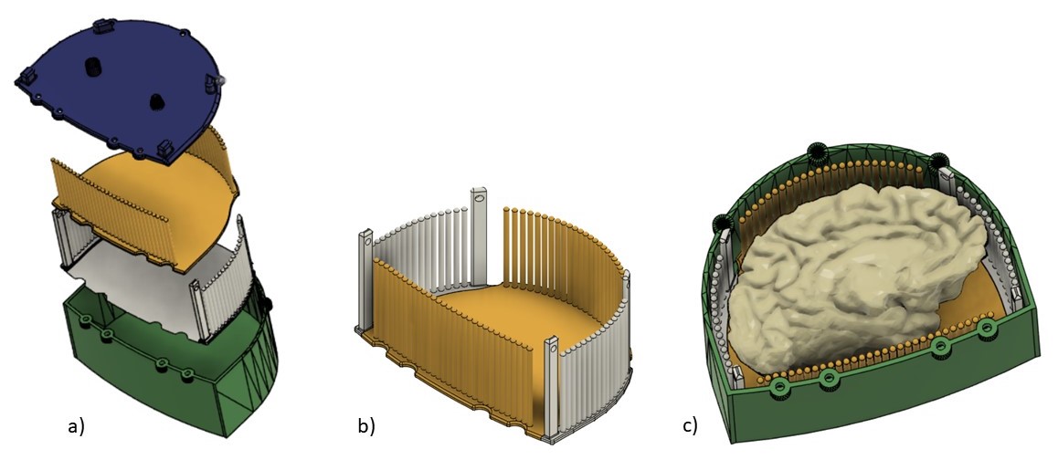
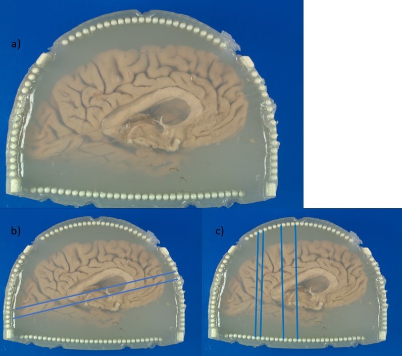
The 3D printed enclosure and cutting guide (Figure 1) loosely conforms to the shape and size of the left hemisphere of the brain with the cerebellum removed, while still having room for varying sizes. The two cutting guide pieces are assembled and inserted into the box. The coronal and axial pieces of the cutting guide are shaped so that they interlock without room for movement while flat in the enclosure and on the cutting table. Heated agarose is then added as the brain, fixed in Paraformaldehyde (PFA) 4% for on average 3 weeks, is inserted into the container (6). Careful attention is given to the filling process, slowly rotating, and deforming the brain slightly as the container is slowly filled to minimize air bubbles as the agar solidifies. Once the brain is submerged in agarose, the lid is screwed in place and additional agarose is added until completely full. The enclosure is set at room temperature for the agarose to solidify. The container is then vacuum sealed and imaged using a 7T MRI scanner (Siemens MAGNETOM). An MP2RAGE: TR=6000ms, TE=4.1ms, Flip Angle=6 and 7 degrees, TI=800 and 2500ms, voxel size=0.4x0.4x0.4mm3 and matrix size=400x514x228 as well as a GRE: TR=40ms, TE1=8ms, TE2=15ms, TE3=21ms, 512 slices and voxel size=0.37x0.37x0.37mm3 are acquired (6). The collected images are then assessed by a pathologist and neuroradiologist to determine desired locations to slice the brain. The four longer posts extend past the walls of the enclosure into the lid. To remove the guide from the enclosure, rods are inserted into the holes of the posts, and the base is held as the rods are used to lift both pieces of the guide out together. The knife cuts between columns (4mm in diameter and spaced 1mm apart) allowing for consistent cuts at 5 mm intervals, or any multiple of 5 mm, in either the axial or coronal orientation. After two axial cuts are made, the cutting guide is separated to remove a slab from the center for gross anatomy imaging. The slab can be removed entirely for separate processing or like in this case inserted to its original position to continue making multiple coronal cuts. The locations of the cuts are noted as in Figure 2b and 2c and used as the reference for MRI registration.Results
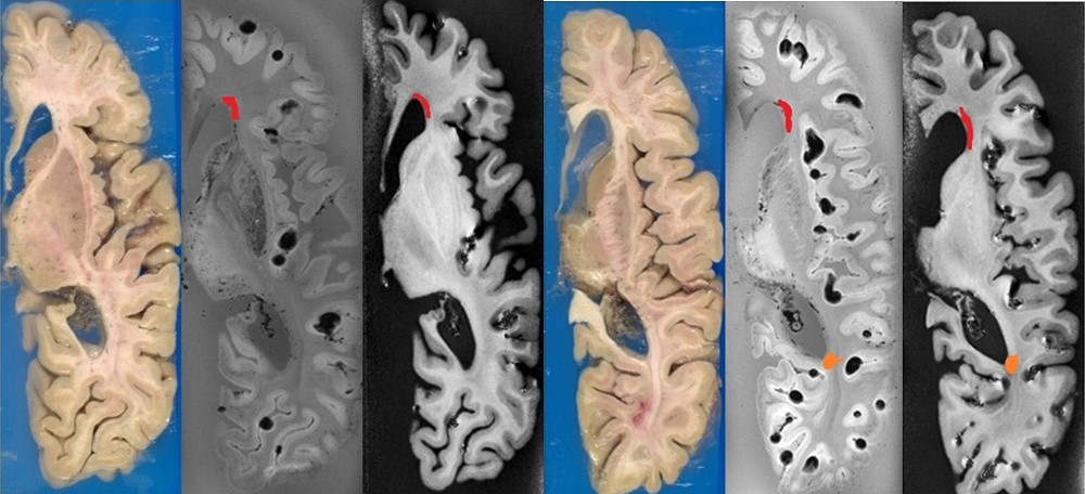
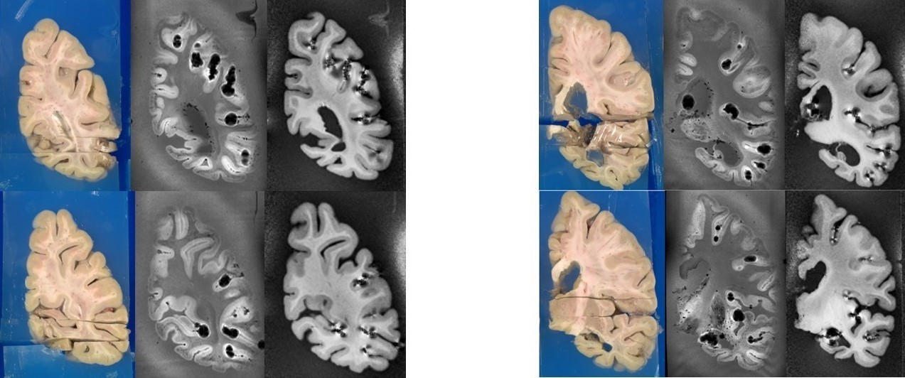
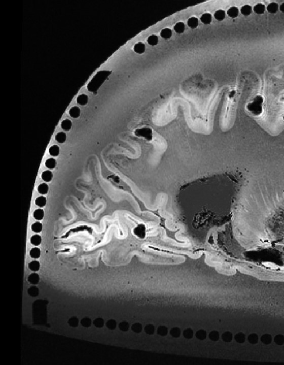
The axial registration can be seen in Figure 3 and the coronal can be seen in Figure 4. The registration of cuts in both the axial and coronal direction are possible with the integration of the separable cutting guide. As the cutting guide is visible in the MR images (Figure 5), we can quickly re-slice the image based on the location of the cuts provided by the pathologist. The use of the cutting guide produces clean cuts with no tissue tearing or brain deformation. Susceptibility artifacts are present in MR images from the air bubbles during the embedding process.Discussion
Our agarose-filled 3D printed box enclosure and integrated separable cutting guide is reusable, fixes the brain in place, and accommodates of varying brain sizes. Additionally, it provides more cutting freedom and precision, fast and accurate registration, and a medium to achieve homogeneous B1, ultimately producing high quality images. 3D printing allows for continuous design feedback and iteration, the formation of thin column structures, future optimizing box shape for B1 and cutting guide designs. The agarose provides a medium for RF signal absorption, minimizing artifacts at the tissue interface as well as allowing for fixation of the brain during the cutting process to achieve consistently orthogonal slices that can quickly be registered to MR images. The cutting guide limits knife orientation orthogonal to the base of the cutting guide, producing perpendicular slabs of brain matter regardless of cutting location.Conclusion
Pathologists are provided freedom to cut the brain in parallel 5 mm slabs as well as on an angle as shown for the axial cuts in Figure 2b. Large scale ex-vivo brain, or possibly organs of similar size, MR imaging and gross anatomy registration has been made feasible with shorter and more accurate registration, reusability of the enclosure and cutting guide, and low-cost material and agarose.Acknowledgements
This work was supported by the National Institutes of Health under award numbers R01MH111265, R01AG063525, T32MH119168, and U19AG068054.References
1. Absinta M, Nair G, Filippi M, et al. Postmortem magnetic resonance imaging to guide the Pathologic Cut. Journal of Neuropathology & Experimental Neurology. 2015;73(8):780-788.
2. Boopathy Jegathambal SK, Mok K, Rudko DA, Shmuel A. MRI based brain-specific 3D-printed model aligned to stereotactic space for registering histology to MRI. 2018 40th Annual International Conference of the IEEE Engineering in Medicine and Biology Society (EMBC). July 2018.
3. Ehrhart M, Wilson C, Selwyn R, et al. Development of a 3D-Printed Brain Holder for Post-Mortem Pediatric Brain MRI at 7T. In proc. Of the 2020 International Society of Forensic Radiology and Imaging Annual Meeting.
4. Luciano NJ, Sati P, Nair G, et al. Utilizing 3D printing technology to merge MRI with histology: A protocol for brain sectioning. Journal of Visualized Experiments. 2016;(118).
5. Singh M, Rajagopalan A, Kim T-S, et al. Co-registration of in vivo human MRI brain images to postmortem histological microscopic images. International Journal of Imaging Systems and Technology. 2009;18(5-6):325-335.
6. Farhat N, Kofler J, Berardinelli J, et al. Reusable 3D printed enclosure with integrated cutting guides for the alignment of ex-vivo MRI with ex-vivo gross brain photographs. In proc. of the 2021 International Society of Magnetic Resonance in Medicine Annual Meeting.
Figures