2323
RF Energy Harvesting System for Autonomous Respiratory Sensor in MRI1Multiwave Imaging, Marseille, France, 2Aix Marseille Univ, CNRS, Centrale Marseille, Institut Fresnel, Marseille, France, 3Aix Marseille Univ, CNRS, CRMBM, Marseille, France, 4IM2NP - UMR 7334 CNRS, Aix-Marseille University, Marseille, France, Marseille, France
Synopsis
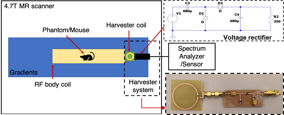
The energy harvesting system was developed for preclinical 4.7 T MRI scanners. The system is composed of a commercial birdcage coil tuned and matched at 200.1 MHz, a harvesting coil and an RF-DC rectifier. The collected energy was used to power a respiratory pressure sensor. The efficiency of the harvesting system was optimized as function of the angular positioning of the harvesting coil in the birdcage. The experiments were carried out with a water phantom and a mouse in vivo. A peak voltage of 1.5V was harvested for 45V input voltage and delivered to a load of 350 Ω.
Introduction
Self-powered sensors could be the next generation of monitoring devices for magnetic resonance imaging (MRI). Employment of these devices will considerably reduce the amount of cables used as well as the cost of powering1, 2, 3. Therefore, we propose an energy harvesting system based on a high-efficiency diode rectifier. The study was performed on a phantom and a mouse in vivo using a preclinical 4.7 T 40 cm scanner (Bruker BioSpin MRI GmbH, Bruker Instruments, Ettlingen, Germany) equipped with a 12cm gradient insert and a 72mm diameter birdcage coil and a 1kW RF power amplifier. The collected energy is used to power a respiratory sensor.Methods and materials
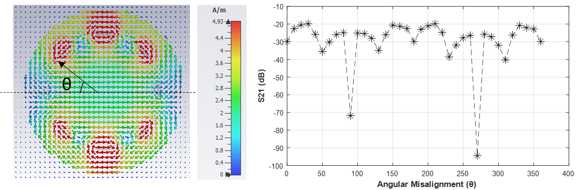
The proposed energy harvesting system is based on near field magnetic coupling between a linearly driven body coil of 72 mm diameter and the harvesting coil of 3 cm diameter. The collected energy is used to power a respiratory sensor (Figure 1). The RF-DC voltage doubler rectifier was designed using Agilent ADS software and implemented on a printed circuit board. The circuit includes Schottky BAT754A SMD diodes for low voltage drop and fast switching and a 680 µF capacitor for power storage. The rectifier output is a load of 350 Ω given by the sensor. The efficiency of the system was optimized using 3D electromagnetic simulation (CST) as a function of the angular positioning of the harvesting coil at the entrance of the birdcage (Figure 2). The distance between birdcage and coil was fixed at 3mm. From the results of the simulations, the birdcage coil generates a transverse magnetic field that is stronger close to its legs. The mutual coupling has to be sufficient to collect energy from the birdcage coil but should not disturb its tuning and matching4 . The coupling is optimal when the coil is perpendicular to the magnetic field lines (θ=30°, θ=150°, θ=210° and θ=330°) and insignificant at θ=90° and θ=270° when the coil is parallel to the magnetic field lines. Therefore, the coil was used at an inclination angle of θ=30°. The experiments were carried out using an RF transmit power attenuation of 20 dBm corresponding to a 45 V RF input voltage. The phantom and the mouse were placed at the center of the birdcage coil in the isocenter of the magnet. Fast Low-Angle Shot (FLASH) images were acquired in sagittal orientation using the following parameters: TE = 6 ms, TR = 100 ms, FOV = 10x10 cm2, matrix 256 x 256, a package of 5 slices and a thickness of 2mm. RF field maps were obtained and transformed into Flip Angle (FA) maps using the 3D Actual Flip Angle Imaging (AFI) sequence6,7 with the following parameters: TE = 2.138 ms, TR1 = 20 ms, TR2 = 100ms, n = 5 , FOV = 10 x 10 x 4 cm3 and matrix of 128 x 128 x 20.Results
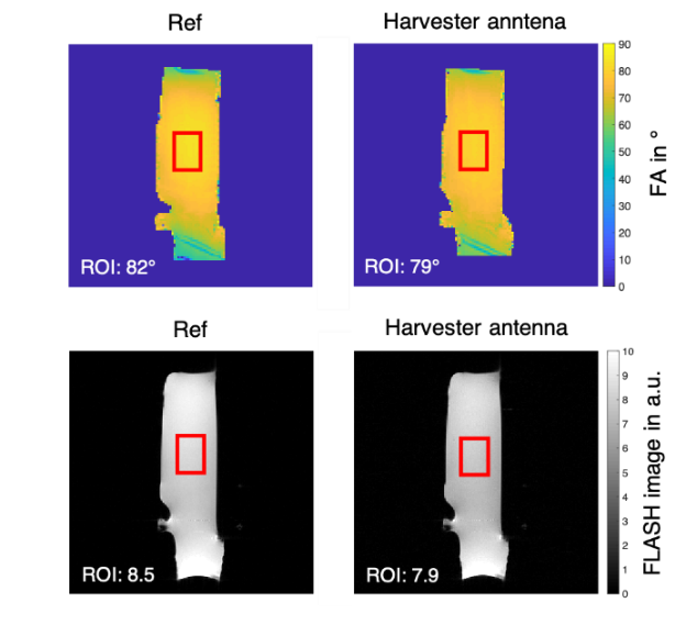
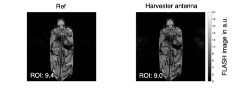
During the image acquisition, a peak voltage of 1.5V was present at the load of 350 Ω. This voltage was enough to power the respiratory sensor, since the minimal voltage required is 1V. The Flip Angle maps in Figure 3 top show the distribution of the RF field. A slight distortion of the body coil’s RF field is seen when using the harvesting system. The mean value of FA calculated inside a ROI at the center of the phantom (red square) showed a 3° decrease when using the harvesting system. In the FLASH images (Figure 3 bottom) a 7% signal loss was obtained, and no artifacts were present. Figure 4 presents the in vivo results of the whole-body FLASH images of the mouse without (left) and with (right) the harvesting system. Similarly, the FLASH images obtained while harvesting energy present no artifacts and a slight signal magnitude reduction of about 4%.Discussion and conclusions
Building a harvesting system requires special care for optimizing the coupling between the system and the MR coil since there is a strong trade-off between harvesting the maximum energy possible and obtaining good quality images. From the literature we know that the harvested energy depends on the mutual inductance between the birdcage and the harvester coil5. A non-matched loop was used in this harvesting system, ensuring that the RF field of the body coil was not disturbed, and quality images could be obtained. The system was able to drive the pressure sensor since the harvested voltage attained 1.5 V at 350 W load. At the same time, the mean value of the FA maps in Figure 3 shows that the disturbance of the RF field was negligible. We observed a loss of only 3° in the FA maps and a loss of 7% in image signal magnitude in the FLASH images. In vivo, signal loss was only 4%. In conclusion, the experiments shown in this work demonstrate the capabilities of the proposed energy harvesting system. It represents an important step in the further development of self-powered sensors for preclinical and clinical MRI, and paves a path towards the use of this technology as a tool for future MRI applications.Acknowledgements
This project has received funding from the European Union's Horizon 2020 research and innovation programme under grant agreement No 736937 first (M-CUBE project), and then under grant agreement No 952106 (M-ONE project); and from the Excellence Initiative of Aix-Marseille University - A*MIDEX, a french "Investissements d'Avenir" programme under Multiwave chair of Medical Imaging and From Institut Carnot STAR.References
1. S.B. Bulumulla, E. Fiveland, K.J. Park, T.K. Foo, C.J. Hardy, Inductively Coupled Wireless RF coil arrays, Magnetic Resonance Imaging 33, 351–357, 2015
2. Lena Nohava, Jean-Christophe Ginefri, Georges Willoquet, Elmar Laistler, and Roberta Frass-Kriegl, “Perspectives in wireless radio frequency coil development for magnetic resonance imaging,” Frontiers in Physics 8 (2020), 10.3389/fphy.2020.00011
3. Jens Höfflin1, Elmar Fischer, Jürgen Hennig, and Jan G Korvink,Energy Harvesting with a figure-8 coil - towards energy autonomous MRI detection, Conference: ENC-Experimental Nuclear Magnetic Resonance Conference, At Asilomar, USA, Volume: 2013
4. Madhav Venkateswaran, Krishna Kurpad, James E. Brown, Sean Fain, and Daniel van der Weide, Wireless Power Harvesting During MRI, IEEE,2020
5. K. Byron et al., An RF-gated wireless power transfer system for wireless MRI receive arrays, Concepts Magn. Reson, Wiley Periodicals, 2018
6. V.L. Yarnykh, Actual flip-angle imaging in the pulsed steady state: a method for rapid three-dimensional mapping of the transmitted radiofrequency field, Magn. Reson. Med. 57 (2007) 192–200.
7. K. Nehrke, On the steady-state properties of actual flip angle imaging (AFI), Magn. Reson. Med.: Off. J. Int. Soc. Magn. Reson. Med. 61 (2009) 84–92.
Figures