2263
Combination of screen printed process with electrodeposition steps to drastically improve flexible MRI coils sensitivity1Université de Lyon, INSA Lyon, Université Claude Bernard Lyon 1, Ecole Centrale de Lyon, CNRS, Ampère UMR5005, Villeurbanne, France, 2Hawkcell, Marcy l'Etoile, France
Synopsis
In the last few years, there has been an increasing interest from the scientific community in the fabrication of flexible coils. Several methods can be used for the manufacture of flexible coil, mainly screen-printed coils on flexible substrates. In this work, three different screen printing coils with different layers of silver ink were manufactured and their quality factors were measured on bench. A MR-coil combining screen-printed process with electrodeposition step was also built. The additional manufacture step allowed improving drastically Q factor of our screen-printed coil with more than one order of magnitude while maintaining good flexibility of the substrate.
Introduction
The MR-coil is the component of the MRI system by which MRI signal is stimulated and received1. This MR-coil is so much more sensitive to tissue signal that it is fitting the shape of the sample 2.However, standard manufacturing process lacks of flexibility and adaptability to fit complex 3D shapes. Therefore, in the past years, the need for new manufacturing methods of MR-coils has become mandatory. Corea et al. [2] presents the first fully functional, screen-printed and flexible MR-coils using PEEK film substrate (75 µm thickness). Due to higher resistivity of silver inks than bulk copper screen-printed process require superposition of layers which may lead to stiffening of flexible substrate and higher risk of layers misalignment. More recently and with a different approach, Gerges et al [3] deposited MR-coil traces directly on the 3D surface of rigid polymer substrates, to build a MRI setup for rodent brain and small samples. In this case, copper traces were built using a combination of electroless deposition with electrodeposition steps which leads to resistivity of traces close to bulk copper. To date, this has not been tested on flexible substrate. Here, we investigate the possibility of using electrodeposition to improve screen printed coils.Methods
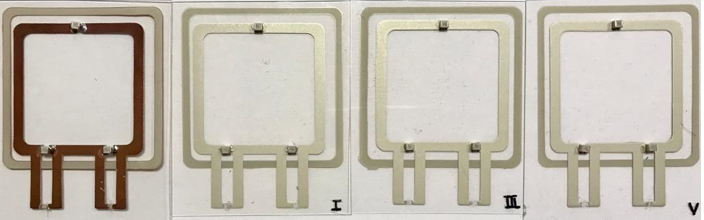
MR-coil geometry was a square with 40mm length and 3mm width. The loop around the MR-coil was made for inductive decoupling when used in a phased array coil. Four MR-coils have been manufactured, on a 500 µm thick polycarbonate substrate, using screen-printed process. Dupont ME603 silver ink was used to deposit 1 layer of tracks for coil (1) and coil (2), 3 layers for coil (3) and 5 layers for coil (4). All coils were then cured at 120°C for 20 min in air. After drying, a copper thickness was deposit on the coil (1) using electroplating. To tune the MR-coil at 64MHz, ceramic capacitors (Exxcelia High Q capacitors) were electrically connected to the coil traces using tin soldering for coil (1) and electrically conductive adhesive (DuPont ME902) for coils (2),(3) and (4). Figure 1 shows a picture of the manufactured MR-coils (1-4). The electrical resistivity ρ of the manufactured coils was calculated using equation : ρ = R A/l, where R is the resistance of the silver trace, which is measured with four-point probe on a length l and cross-sectional area A measured using an optical profilometer (Nano-Point-Scanner (NP3)).For the comparison purposes, the same coil was made by using an FR4 substrate (coil (5)).
The coil sensitivity was evaluated from measurement of the unloaded quality factor. This was performed using the single loop method4 with a Vector Network Analyzer (R&S ZNL3) and a homemade 1cm diameter coaxial loop.
Results
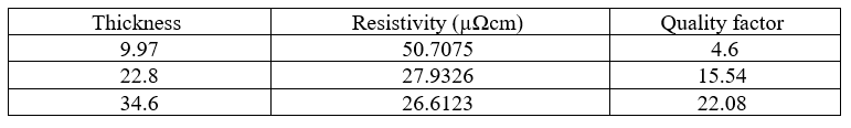
As expected, the resistivity of the MR-coil decreases when increasing the amount of silver layers (Table 1). The measured quality factors increase when adding more layers of silver ink (Table 1). The electrodeposited coil has a low resistivity and a high conductance (equivalent to copper) and presented of 165 which was similar to the one obtained with the FR4 substrate, of 158. Qualitatively, flexibility of the substrate seemed not to be altered by the electroplating of the one layer screen-printed coil.Discussions
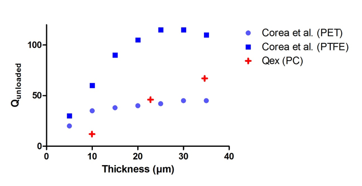
In order to compare our results with Corea et al. [5], the measured Q factors of MR-coils (1-3) were extrapolated using scaling rule defined in Darrasse et al [6] for non-conductive samples. The Q factor scale with the product of the square root of the frequency by the size of the MR-coil. Figure 2 presents a superposition of Corea’s results and our measurements with similar values. The MR-coils made with PC has similar Q factor than the ones reported in [5] using a PET substrate which can be explained by similar dielectric loss for both substrate. Nevertheless, our manufactured MR-coil has a quality factor that has not reached a stable value which should be investigated in further studies by increasing thickness deposit. The electroplating step allowed improving drastically Q factor of our screen-printed coil with more than one order of magnitude. The designed and characterized coils will be tested in imaging condition on a 1.5T MRI with a phantom to validate the increased signal to noise ratio compared to screen printed coils.Acknowledgements
The financial support provided by Ingénierie@Lyon, member of the Carnot Institutes Network (Metafab 3D project) for the postdoctoral scholarship of Dr T. Gerges is acknowledged.References
1. Vaughan, J. T. & Griffiths, J. R. RF Coils for MRI (JohnWiley and Sons Ltd., 2012).
2. Corea, J. R. et al. Screen-printed flexible magnetic resonance imaging receive coils. Nat. Commun. 7:10839 doi: 10.1038/ncomms10839 (2016).
3. T. Gerges, V. Semet, P. Lombard, S. Gaillard, M. Cabrera, et S. A. Lambert, « 3D Plastronics for Smartly Integrated Magnetic Resonance Imaging Coils », Front. Phys., vol. 8, p. 240, juill. 2020, doi: 10.3389/fphy.2020.00240.
4. J.-C. Ginefri, E. Durand, et L. Darrasse, « Quick measurement of nuclear magnetic resonance coil sensitivity with a single-loop probe », Review of Scientific Instruments, vol. 70, nᵒ 12, p. 4730‑4731, déc. 1999, doi: 10.1063/1.1150142.
5. J. R. Corea, P. B. Lechene, M. Lustig, et A. C. Arias, « Materials and methods for higher performance screen-printed flexible MRI receive coils », Magn. Reson. Med., vol. 78, nᵒ 2, p. 775‑783, août 2017, doi: 10.1002/mrm.26399.
6. L. Darrasse et J. -. Ginefri, “Perspectives with cryogenic RF probes in biomedical MRI,” Biochimie, vol. 85, n°. 9, p. 915-937, Sep. 2003.
Figures