2262
Effect of Matching Network Losses on preamplifier decoupling circuit topologies at room and cryogenic temperature for 3 T 13C applications1Department of Electrical Engineering, Technical University of Denmark, Kongens Lyngby, Denmark, 2Department of Health Technology, Technical University of Denmark, Kongens Lyngby, Denmark
Synopsis
The SNR performances of a three- and a four-element matching circuit topologies are compared for the case of 3 T 13C imaging. The benefit to SNR of cryogenic cooling is also compared against the choice of matching networks. Results show that while cryogenic cooling can improve the output SNR by 2–3 dB, a less lossy matching network design can improve the SNR performance by 7–8 dB. The importance of matching network design ought not to be dismissed.
Introduction
Preamplifier decoupling is widely used as a decoupling technique in coil arrays1. To decouple coils, matching/decoupling networks that present a high impedance to coils are built, among which three-2 and four-element matching networks3 already have explicit design equations. While they perform equally well in lossless cases, how their performance changes in lossy cases remains to be studied. This abstract compares the performance of a three- and a four-element matching network in terms of final output signal-to-noise ratio (SNR) and investigates the importance of temperature relative to the choice of matching networks by cryogenic cooling to -169°C (104 K).Methods
To evaluate SNR performance of three- and four-element matching networks at room and cryogenic temperature, an oval coil4 for mouse imaging shown in Figure 1(a) is matched to WMA32C preamplifiers (WanTCom, Chanhassen, MN, USA) at 32.13 MHz, the resonance frequency of 13C at 3 T. The loaded coil impedance at room temperature is Zcoil = 37.1 mΩ + j11.7 Ω. Matching schemes are shown in Figure 2(a). Three- and four-element matching networks are built by design equations2,3. For three-element matching, the T structure as shown in Figure 2(b) is selected as the Π structure contains two inductors. For four-element matching, the structure in Figure 2(c) is used with $$$L_4=L_4^\prime=150\textrm{ nH}$$$. Air-core inductors from Coilcraft Inc. (Cary, IL, USA) and high-Q capacitors from Passive Plus Inc. (Huntington, NY, USA) are used. Both networks are symmetric.Circuits at room temperature are EM co-simulated by Advanced Design System (Keysight Technologies, Santa Rosa, CA, USA). Printed circuit boards (PCBs) are designed and fabricated. During experiments at both room and cryogenic temperature, inductors and capacitors are adjusted to obtain optimal noise impedance of 50 Ω at the output and maximum decoupling at the input, all at 32.13 MHz, as shown in Figure 2(a).
Next, all coils, room-temperature coils included, are mounted in the same place in the cryostat shown in Figure 1(c) one at a time to ensure measured SNRs are comparable. For cryogenic experiments, coils are cooled by liquid nitrogen to -192°C (81 K), and PCBs are cooled to -169°C (104 K), at which the temperature is kept throughout each measurement. For room-temperature experiments, the cryostat is not cooled. The cryostat is placed inside a shielded box. Signal is excited by a signal generator (SMC100A, Rohde & Schwarz, Munich, Germany) and received by a spectrum analyzer (E4440A, Keysight Technologies).
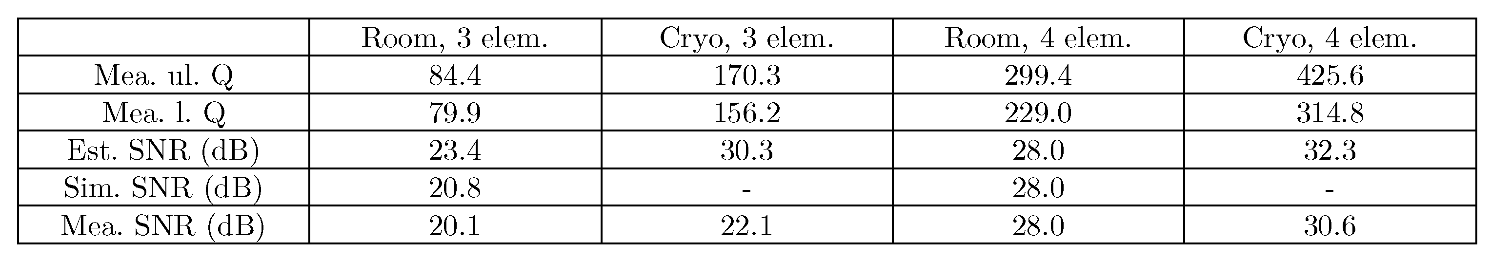
Coil Qs, both unloaded and loaded when connected with matching networks, are measured by a double-loop probe connected to a vector network analyzer (ZNL3, Rohde & Schwarz)1. For simplicity, active decoupling circuitry is not installed. The output SNR improvement is estimated by coil Qs5: $$\mathrm{\Delta}\mathrm{SNR} \left( \text{dB} \right) = 10 \times \lg\frac{T^{\left( r \right)}Q_{l,\text{ref}}^{\left( r \right)^{- 1}} + T^{\left( r \right)}Q_{s,\text{ref}}^{\left( r \right)^{- 1}}}{T^{\left( c \right)}Q_{u}^{\left( c \right)^{- 1}} + T^{\left( r \right)}Q_{s}^{\left( c \right)^{- 1}}},$$ where T denotes temperature; superscripts (r) and (c) denote room-temperature and cryogenic quantities; subscripts l, s, u denote loaded, sample, and unloaded quantities. The reference (subscript ref) is four-element matching at room temperature.
Results
Simulated and measured SNRs are shown in Figure 3. SNRs for three-element matching are significantly lower than the four-element matching. At room temperature, the three-element SNR lags behind the four-element SNR by 7.9 dB. The lag is predicted to be 7.2 dB by simulation, which agrees well with the measurement. The three-element SNR improves by 2.1 dB at cryogenic temperature, and four-element SNR improves by 2.6 dB. The three-element SNR, however, further lags behind the four-element SNR by 8.5 dB.Coil Qs are also significantly lower for three-element matching. In this case, SNR prediction by coil Q over-estimates the SNRs of three-element matching.
Discussion
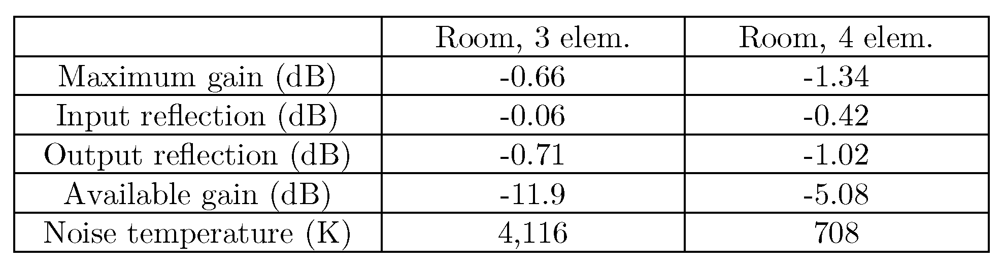
Measured Qs do not predict the SNR lag of three-element matching, especially at cryogenic temperature; besides, they over-estimate the SNR improvement of four-element matching at cryogenic temperature. This is because the estimation method assumes perfect coil matching, which is not the case in reality. Nonetheless, a low or high coil Q still signals high or low output SNR.From the results, inappropriate choice of matching networks can result in SNR loss irremediable by cooling. This can in part be explained by matching network gain, as shown in Figure 4. Although the three-element matching network in Figure 2(b) is intrinsically less lossy than its four-element counterpart in Figure 2(c), as is shown by the maximum gains in Figure 4, the available power of the matching network is 6.8 dB less than the four-element network. This means more noise comes from the matching network because for a passive two-port network,
$$T_{e} = \left(\dfrac{1}{G} - 1 \right)T_{0},$$
where T0 = 290 K is the room temperature, Te is the equivalent noise temperature of the matching network, and G is the available power gain6.
Conclusion
The SNR performances of a three- and a four-element matching network are compared at room and cryogenic temperature. In this case, the four-element matching improves output SNR by 7.9 dB mainly by increasing power delivery from a coil to a preamplifier. Cryogenic cooling improves the SNR by 2–3 dB. Matching networks deserve careful design.Acknowledgements
No acknowledgement found.References
1. Roemer PB, Edelstein WA, Hayes CE, Souza SP, Mueller OM. The NMR phased array. Magn Reson Med. 1990;16(2):192-225. doi:10.1002/mrm.19101602032. Wang W, Zhurbenko V, SánchezHeredia JD, ArdenkjærLarsen JH. Three element matching networks for receiveonly MRI coil decoupling. Magn Reson Med. 2021;85(1):544-550. doi:10.1002/mrm.28416
3. Reykowski A, Wright SM, Porter JR. Design of Matching Networks for Low Noise Preamplifiers. Magn Reson Med. 1995;33(6):848-852. doi:10.1002/mrm.1910330617
4. Sánchez‐Heredia JD, Baron R, Hansen ESS, Laustsen C, Zhurbenko V, Ardenkjær‐Larsen JH. Autonomous cryogenic RF receive coil for 13C imaging of rodents at 3 T. Magn Reson Med. 2020;84(1):497-508. doi:10.1002/mrm.28113
5. Sanchez-heredia JD, Søvsø E, Hansen S, Laustsen C, Zhurbenko V, Ardenkjær-larsen JH. Low-Noise Active Decoupling Circuit and its Application to 13 C Cryogenic RF Coils at 3 T. Tomography. 2017;3(1):60-66. doi:10.18383/j.tom.2016.00280
6. Pozar DM. Chapter 10: Noise and Nonlinear Distortion. In: Microwave Engineering. 4th ed. John Wiley & Sons, Inc.; 2011:496-523.
Figures
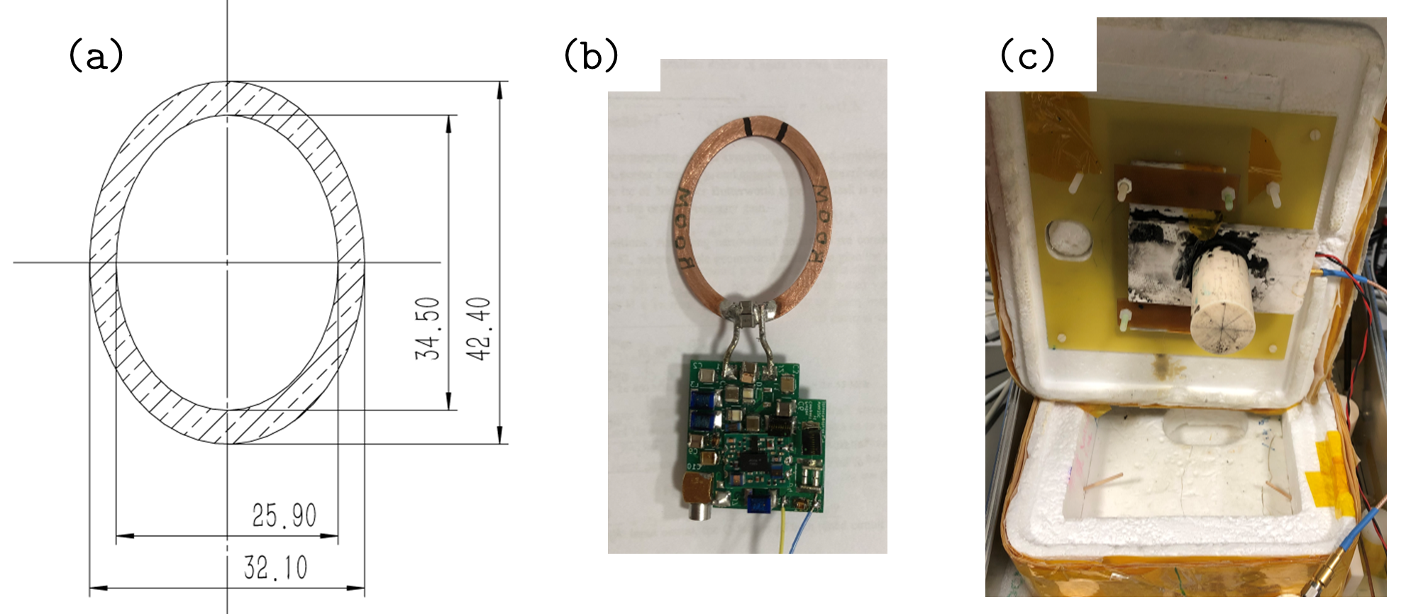
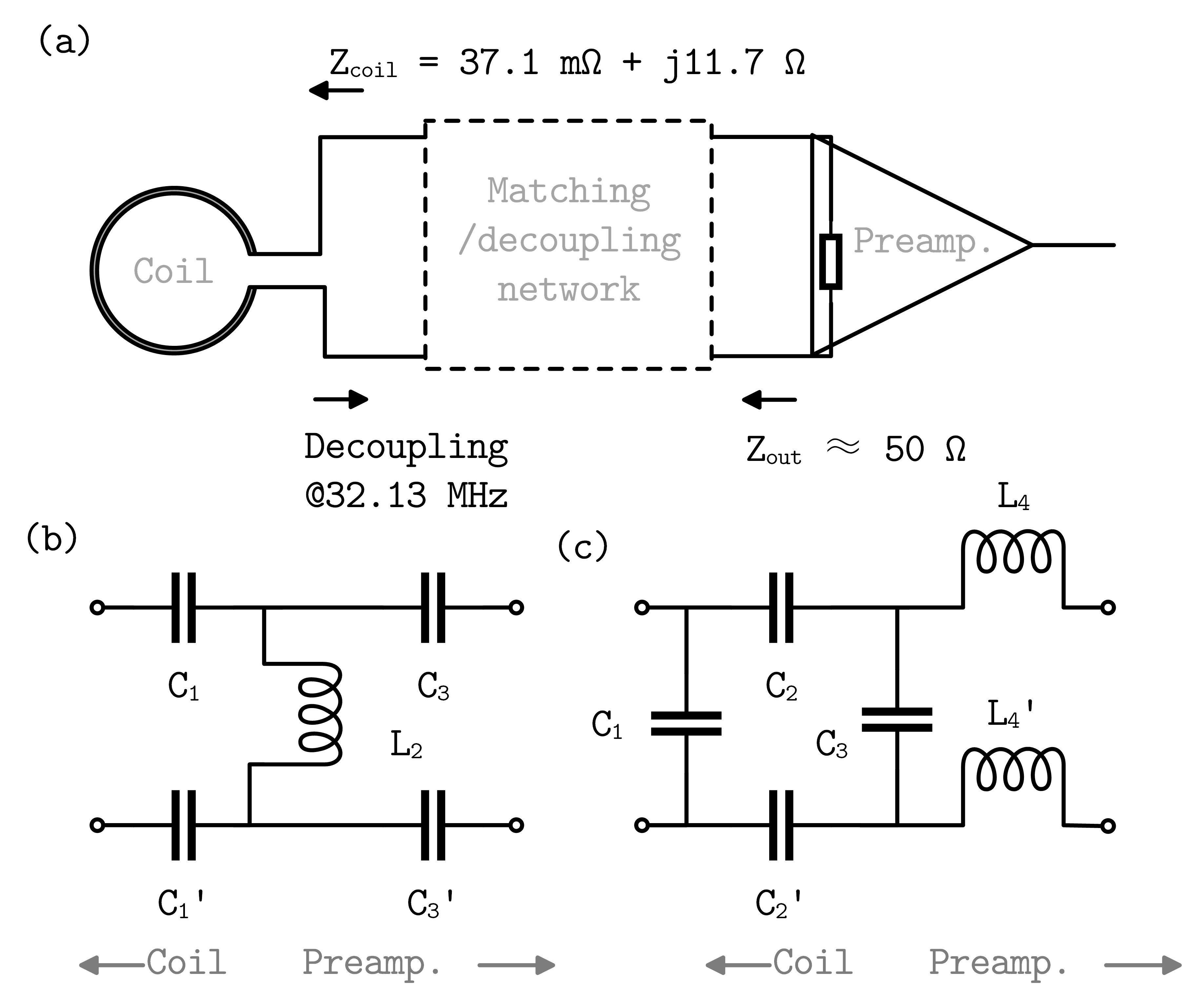
Figure 2. (a) The matching networks exhibit Zout ≈ 50 Ω and give maximum decoupling at 32.13 MHz. (b) The symmetric three-element matching network. At room temperature values $$$C_1^\prime = C_1 = 552\textrm{ pF}$$$, $$$L_{2} = 16\text{ nH}$$$, $$$C_{3}^{'} = C_{3} = 1,490\textrm{ pF}$$$. (c) The symmetric four-element matching network. At room temperature values $$$C_1^\prime = C_1 = 459\textrm{ pF}$$$, $$$C_2^\prime = C_2 = 23\textrm{ pF}$$$, $$$C_3 = 66\textrm{ pF}$$$, $$$L_4^\prime = L_4 = 150\textrm{ nH}$$$.