2261
Flexible Receive Array of Parallel-Resonance High-Impedance Coaxial Coils for 13C Imaging1Techical University of Denmark, Kgs. Lyngby, Denmark
Synopsis
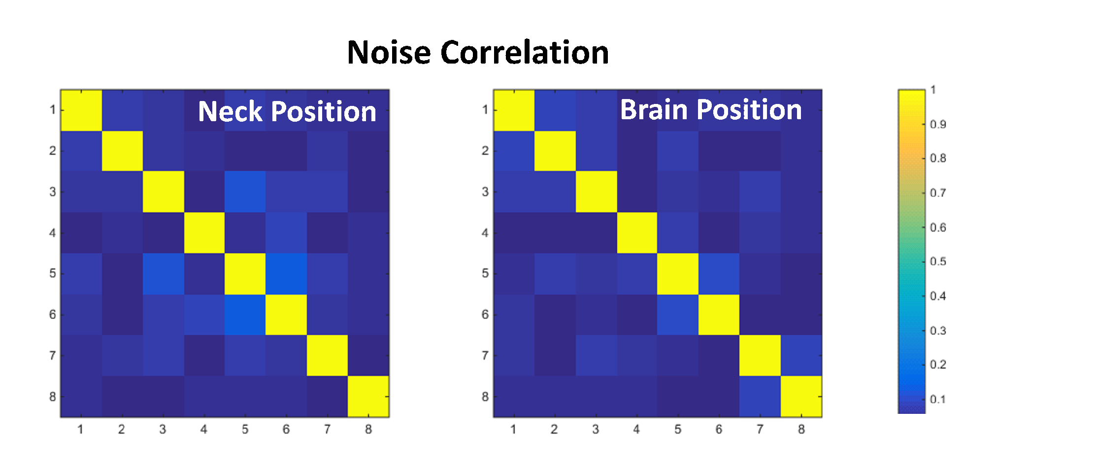
Self-resonant coils are well suitable for flexible array design. The size of such coils is dictated by the RF signal wavelength, which makes the design challenging at low frequencies. In this work, 13C tuning is achieved by combining distributed and lumped capacitance with the self-inductance of an RG-178 coaxial cable. A 1H trap is moved from the coil to the board of the preamplifier for better coil flexibility. The active 13C decoupling circuit is compact and broadband. The approach is used to develop a flexible 8-channel receive array of parallel-resonance coils for 13C-imaging. The array elements exhibit low noise correlation.
Introduction
MRI coils are typically operated either in an inductive or a self-resonant mode. The self-resonant coils can exploit a series or a parallel resonance and are often adopted as elements of flexible arrays1,2. One example of a series resonance coil is AIR coils from GE1. Parallel resonance coils can be realized using coupled conductors of a coaxial cable and have a high input impedance at resonance. Therefore, they are sometimes referred to as high-impedance coils2. (It could also be noted, that the coils with distributed parameters exhibit periodic behavior of input impedance and, in general, the same structure can be used in series as well as parallel resonance modes – this is particularly useful in high-field, high-frequency applications). The use of self-resonant coils at low frequency is challenging and requires longer conductor length3. In this work, we use a different approach to achieve self-resonant coil tuning by combining distributed and lumped capacitors along with the self-inductance of an RG-178 off-the-shelf coaxial cable. This approach is used to design a flexible parallel-resonance 13C imaging coil operating at 32.1 MHz. The further advantages of using such a coil: 1H decoupling can be integrated on the preamplifier Printed Circuit Board (PCB) instead of the loop wire; it allows a simple broadband active decoupling network, which further supports flexible coil implementation. The coil is used as an element of an 8-channel array. The performance of the flexible array is evaluated in various imaging scenarios.Methods
The coil is a loop of 8 cm in diameter4. It is constructed out of RG-178 1.8 mm jacket diameter coaxial cable and is used in parallel resonance. In order to tune the coil to the desired frequency, a lumped capacitor Ct = 90.2 pF is connected across the gap in the outer conductor of the cable, as illustrated in Fig. 1. This tuning allows to use any coaxial cable for coil construction5 and therefore a standard 50 Ω coaxial cable could be implemented in this design.At the resonance frequency of 32.1 MHz the input impedance of the coil is purely real: Zc = Rc ≈ 1.8 kΩ (when sample loaded).
In order to prevent an inductive coupling to the 1H coils of the scanner, a trap is included in the outer conductor of the coaxial cable. The decoupling measurement results using a double-loop probe in the vicinity of the coil are shown in Fig. 2.
When the coil is actively decoupled (the pin diode in Fig. 1 is forward biased shorting the input of the coil resonator), a local minimum appears at 127.8 MHz, which is the operation frequency of 1H coils in GE 3T scanners. A passive, preamplifier decoupling at 13C is based on the same principle of spoiling the resonance. This is achieved by presenting a low impedance Rs at the coil terminals. A 3-element matching and decoupling circuit is designed using equations derived by Wang6,7. This circuit transforms the coil impedance Rc into the optimal noise impedance of the Low Noise Amplifier8 (LNA in Fig. 1) Zn,opt, and, at the same time, transforms the input impedance of the LNA Za to a lowest possible impedance Rs. As can be seen in Fig. 2, the circuit provides a passive decoupling (when diode is reverse biased) resulting in a local minimum in the double-loop probe measurements at 13C frequency. The footprint of the entire preamplifier board is only 15 mm x 16 mm, and is small compared to the size of the loop making it useful in flexible multichannel array applications.
Results
To demonstrate the concept, 8-channel flexible array has been constructed. A photograph of the array is shown in Fig. 3(a). To minimize a coupling between neighbor channels, coils were critically overlapped. The optimal overlapping was found empirically by measuring SNR as a function of edge-to-edge distance between two neighbor loops in the array. The results of the measurements are shown in Fig. 3(b).As can be observed, the SNR is recovered when the coils are overlapped by approximately 20 mm, which corresponds to 25% of the loop diameter. This is similar to what is typically observed in conventional inductive loop coils.
To test the imaging properties of the flexible array in different imaging scenarios, the array was applied to a human head phantom4 at a brain and neck positions. The photograph of the two imaging setups as well as corresponding imaging results are shown in Fig.4. The measured noise correlation matrix for both imaging scenarios is shown in Fig. 5.
Discussion and Conclusion
Self-resonant high-impedance coaxial coils allow for convenient integration of decoupling networks compatible with flexible coil implementation. Hybrid co-integration of lumped and distributed components in self-resonant coils allows to tune the coaxial coil to virtually any frequency. This is particularly useful in low-frequency applications. The approach is used in the design of an array of parallel-resonance coils operating at 32.1 MHz. The array is flexible, lightweight and easy to handle due to flexibility of the implemented cable and compact preamplifier design with integrated noise matching as well as passive and active decoupling. The array is suitable for imaging various body parts and demonstrates low noise correlation.Acknowledgements
The authors would like to thank the Danish National Research Foundation (grant DNRF124) for partial support of the activities.References
1. McGee K.P. et al, “Characterization and evaluation of a flexible MRI receive coil array for radiation therapy MR treatment planning using highly decoupled RF circuits,” 2018 Phys. Med. Biol. 63 08NT02.
2. Zhang B, Sodickson DK, Cloos MA., “A high-impedance detector-array glove for magnetic resonance imaging of the hand,” Nature Biomedical Engineering, 2, pp.570-577, 2018.
3. Czerny R., Nohava L., Frass-Kriegl R., Felblinger J., Ginefri J.-C., and Laistler E., “Flexible multi-turn multi-gap coaxial RF coils: enabling a large range of coil sizes,” Proceedings of ISMRM 27th Annual Meeting, Montreal, Canada, 11-16 May, 2019, program # 1550.
4. Sanchez-Heredia J. D., Wang W., Olin, R. B., Zhurbenko V., and Ardenkjær-Larsen, J. H., “Enhanced Low Frequency MRI using Flexible Shape Arrays Made of Standard Wire,” Proceedings of 14th European Conference on Antennas and Propagation. IEEE, 2020, 4 p.
5. Zhurbenko V., Sánchez-Heredia J.D., Wang W., Ardenkjær-Larsen J.H., “Flexible Self-Resonant Detector Coil for Magnetic Resonance Imaging of Carbon-13,” Proceedings of 50th European Microwave Conference, January 12-14, 2021, Utrecht, The Netherlands, pp.112 115.
9. Sanchez-Heredia J. D. et al, “Multi-site benchmarking of clinical 13C RF coils at 3T,” Journal of Magnetic Resonance, 2020, vol. 318, 106798.
Figures
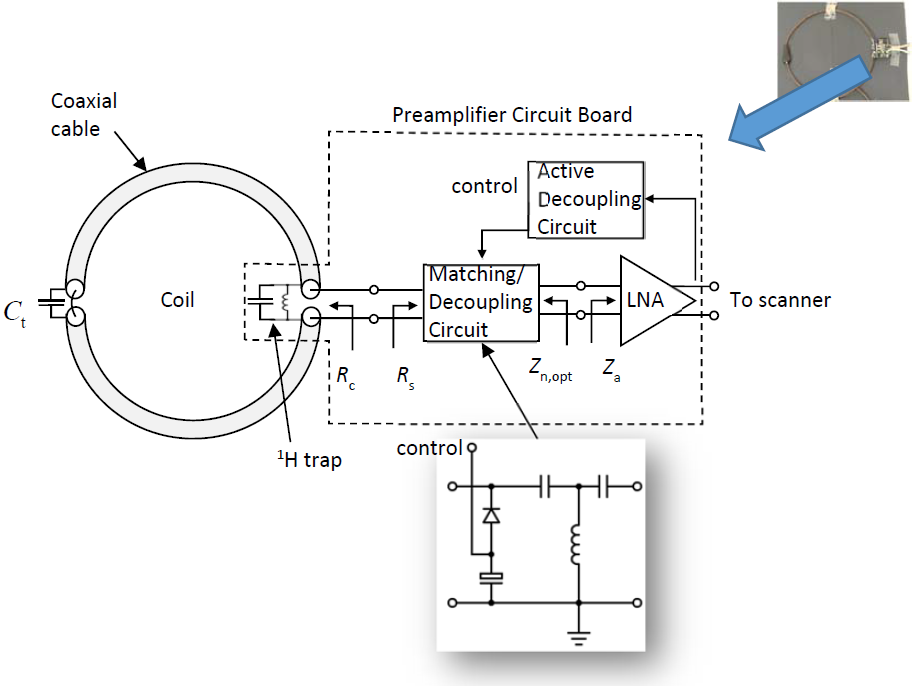
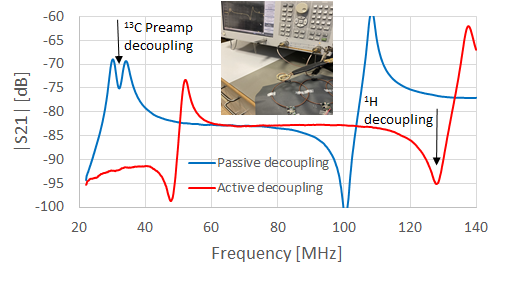
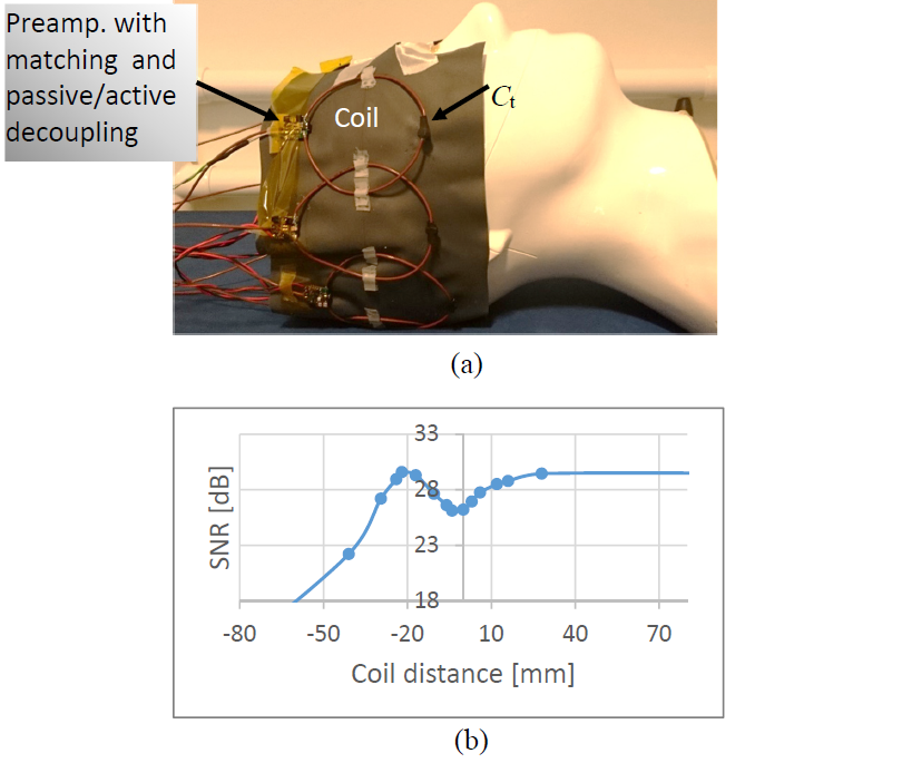
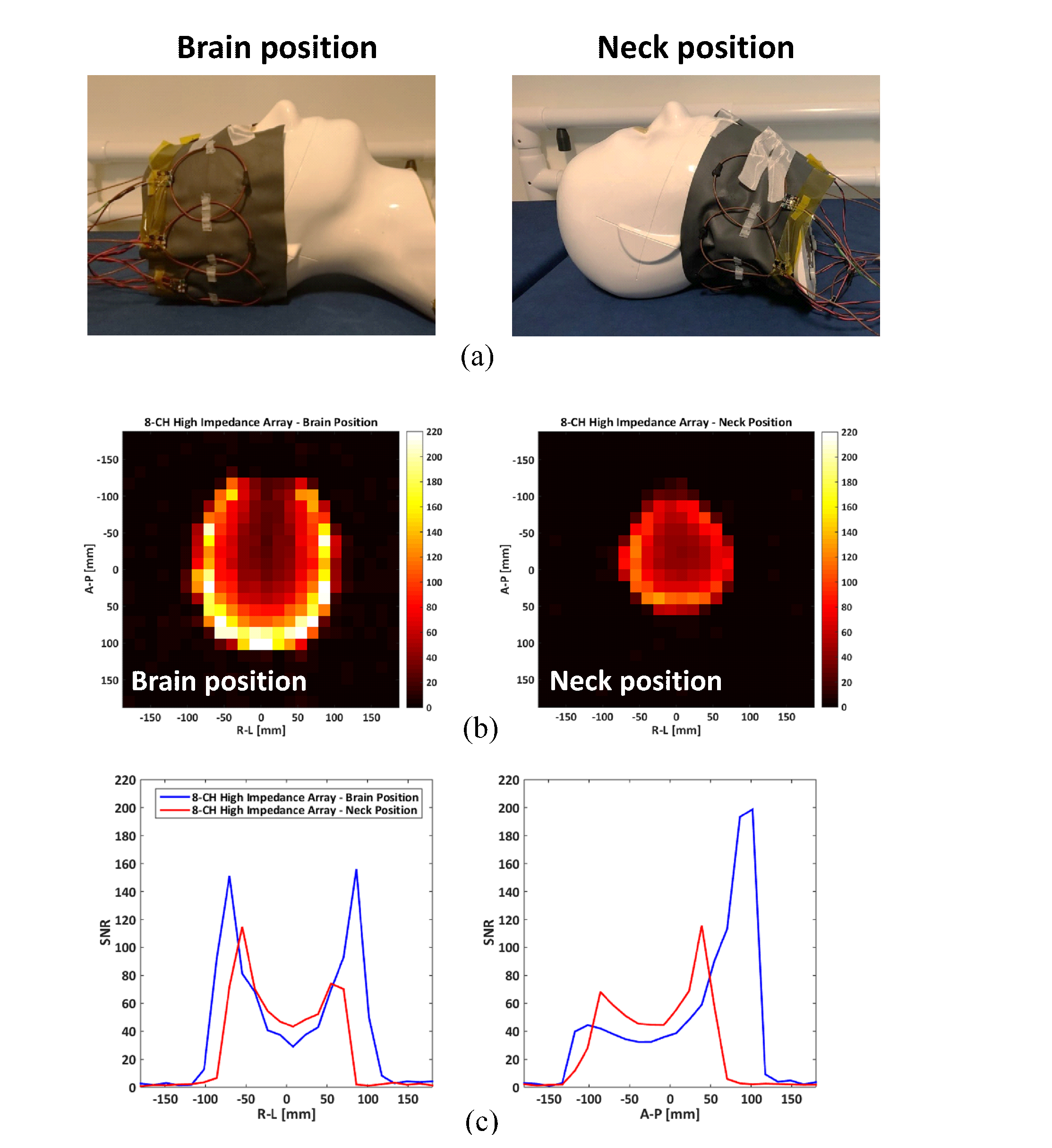
Fig. 4. Imaging experiments in GE 3T scanner using procedure described in 9. (a) Photograph of the setup for imaging brain and neck areas. (b) SNR map for 8‑channel parallel-resonance array. Cross-section through the phantom perpendicular to the plane of the loop. (c) Anterior-Posterior (A-P) and Right-Left (R-L) axis.
The array length is ~50cm while phantom head perimeter is ~60cm, so the phantom could not be covered entirely. This is the reason for the darker area on the top of the first image, where there is no active element.