2256
Optimization and Analysis of Shielded Loop Resonators towards Modular Coil Arrays1Dept. Radiology, Medical Physics, Medical Center - University of Freiburg, Freiburg, Germany
Synopsis
Light-weight and flexible RF coil arrays are needed to obtain high SNR which is translated into shorter scan times and to increase patient compliance. Transmission line resonators or shielded loop resonators (SLR) are insensitive to the changes in geometry and form, since the tuning is determined by the length of the transmission line. In this study, we propose two parameters and a test setup to evaluate coaxial cables and relate this to the SLR performance. Modularity is demonstrated on facial coil that can be attached to the face masks.
Introduction
Light-weight and flexible RF coil arrays are needed to obtain high SNR which is translated into shorter scan times and to increase patient compliance. Various techniques exist to obtain flexibility in conventional loop coils[1],[2], but tuning of loop coils is sensitive to geometry enforcing a trade-off between the flexibility and coil performance. Transmission line resonators or shielded loop resonators (SLR)[3] are however insensitive to the changes in geometry and form, since the tuning is determined by the length of the transmission line (e.g. coaxial cable or strip-line)[4]–[8].So far the imaging performance of the SLRs has only been evaluated for various coaxial cables, and a metric to determine and optimize the performance is still missing. In this study, we propose two parameters and a test setup to evaluate coaxial cables and relate this to the SLR performance. We also show that SLRs perform better at self-resonance. Finally, a flexible, modular SLR array is presented that can be attached to a medical mask for facial MRI, or combined to form a shoulder coil array without tuning/geometrical adjustments.
Methods
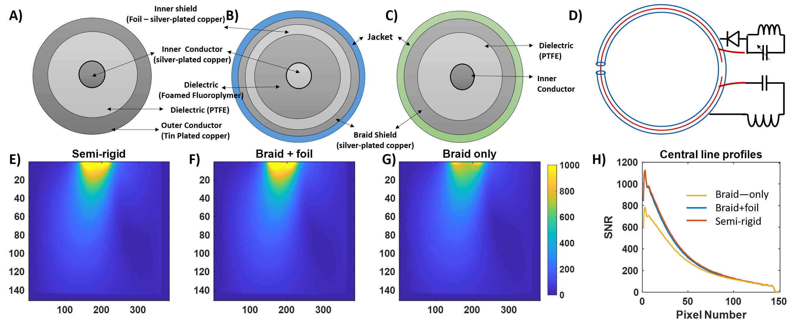
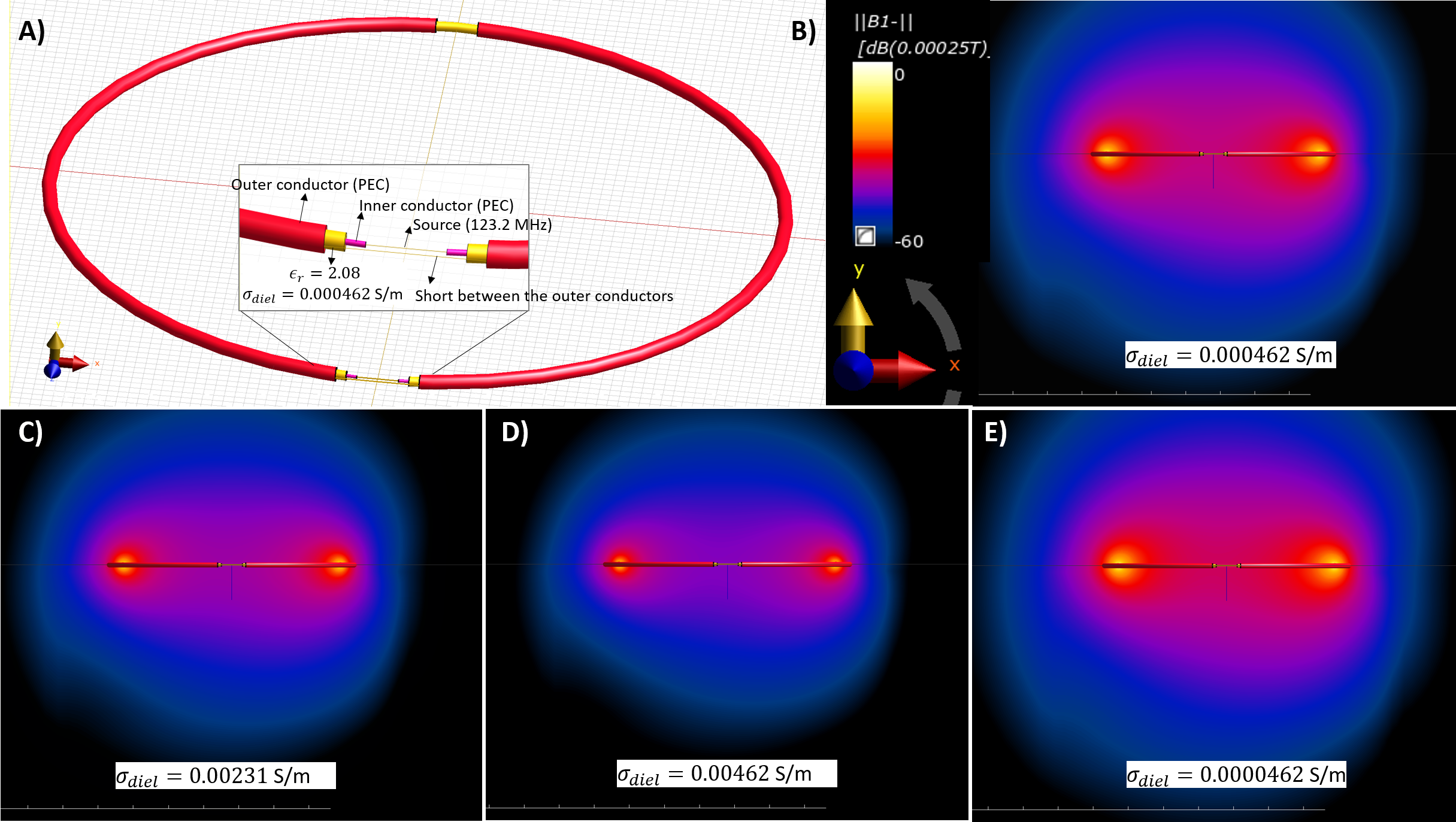
A single-gap SLR is driven differentially through its inner conductors: electromagnetic fields couple to the outer surface of the outer conductor and a magnetic field is generated forming a sensitivity profile similar to loop coils. The coil sensitivity is directly related to the surface current distribution. The lower the resistance on the outer surface of the shield, the higher is the surface currents, thus sensitivity. Surface currents can be computed via numerical/analytical modeling[9]. However, for braided cables, with limited accuracy[10]. Shielding effectiveness of coaxial cables is also related to the resistance at the outer surface of the outer conductor, which can be quantified by transfer impedance measurement[11]. Here, we propose to measure the SLR performance via a S21 measurement, which is adapted from a transfer impedance evaluation setup from [12]. In Fig.1,the coaxial cable under test (CUT) is shaped in a half circle and soldered or connected to the connectors available at the ground plate. Ground plate prevents direct coupling of the sniffer loop to the cables. One end of the CUT is terminated, the other end is connected to the network analyzer. In case of a weak shield (e.g., loose braiding with large openings), S21 would read high values. Low surface resistance, thus strong shielding would however prevent RF signal emitted from the sniffer loop to couple to the inner conductor. We compared SLRs made of different shielding materials (Fig.2A-C) in shielding effectiveness and MR imaging performance (i.e.,SNR).Another metric for performance evaluation is the loss tangent, tanδ, of the dielectric core, defined as the ratio of dielectric permittivity and effective dielectric conductivity. Lower dielectric conductivity σdiel results in lower loss tangent, higher Q-factor and better coil performance. To demonstrate its importance in SLR performance, we simulated a 29awg SLR model using the FDTD solver of Sim4Life 6.2 (ZMT, Zurich) for different σdiel (Fig.3A).
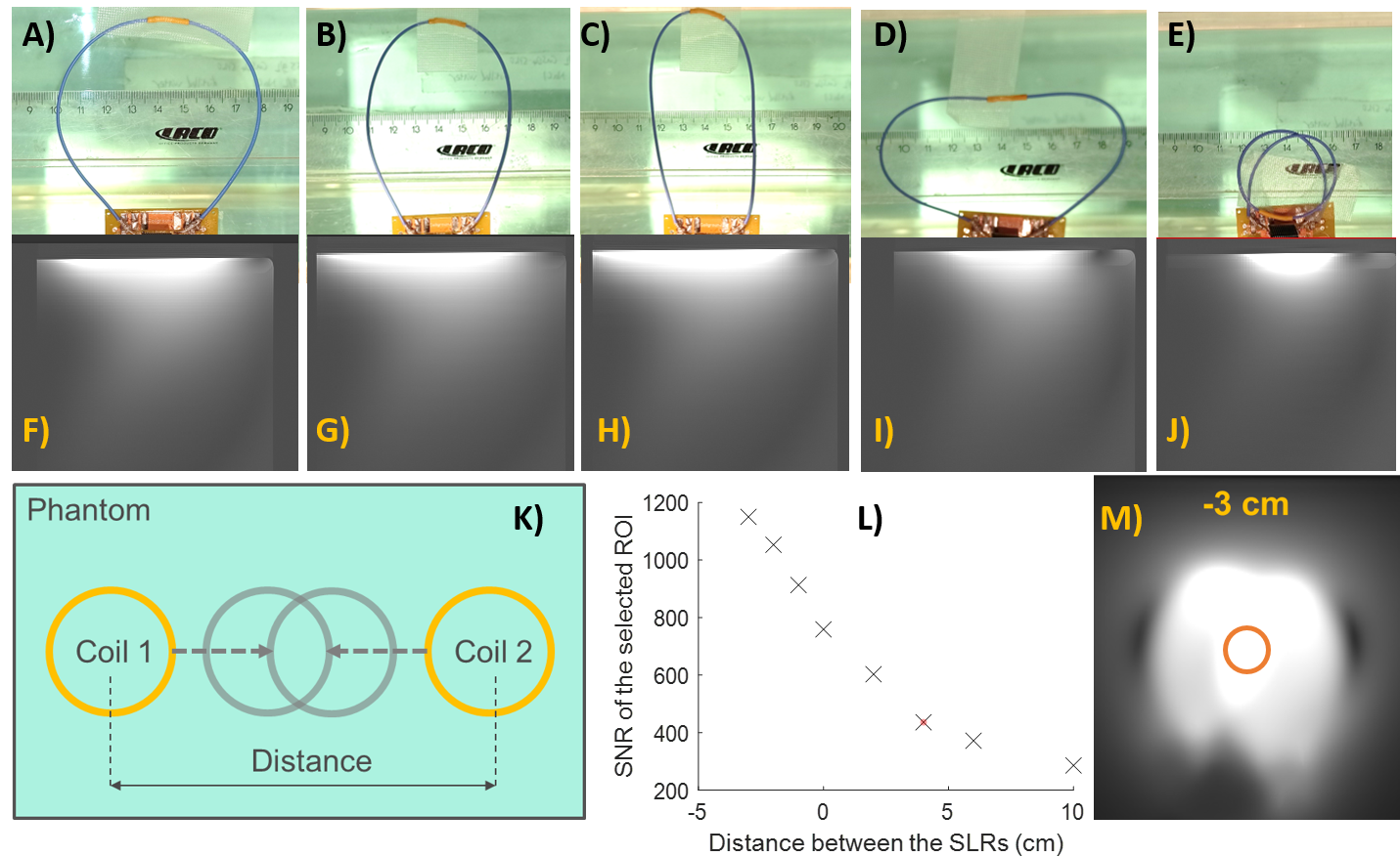
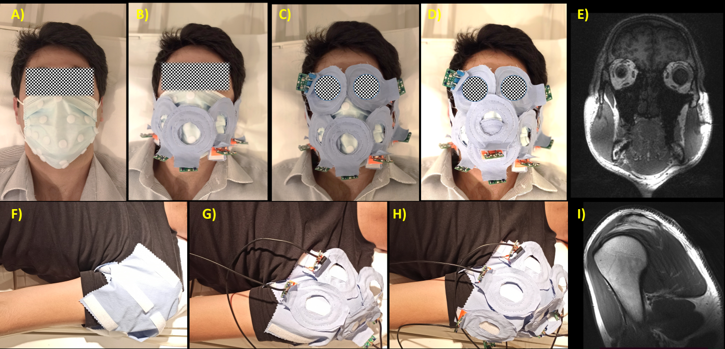
We compared SLRs made of cables shorter and longer than the resonant length made by nonmagnetic coaxial cables of 29awg sizes: Braiding-only, braided with metal foil and a semi-rigid as shown in Fig.2A-C. SLRs were constructed at different cable lengths of 28,26,24,22,20,18 cm to determine the self-resonant mode where no tuning element is required (Fig.2D). The prototype coils were tested on a clinical 3T MRI system (Prisma, Siemens, Germany) in a homogeneous phantom for flexibility(Fig.4A-J) and coupling(Fig.4K), and a human volunteer on facial MRI (Fig.5A-D). Finally, shoulder MRI was demonstrated using the modular coils (Fig.5F-H).
Results
As expected, the shielding effectiveness of the semi-rigid cable was 21 and 26dB higher than that of the flexible braided and braided+foil cable, respectively (Fig.1B). Simulations show that the sensitivity of the SLR element will increase with decreasing σdiel (Fig.3B-E). In Fig.2E-H, SNR maps and line plots show that semi-rigid and braided+foil SLR provides up to 42% higher SNR than the braided-only SLR, especially near the coil plane.Among the SLRs made of 18:28cm cables, 22cm-SLR was self-resonant and performed better in SNR compared to other lengths (images not shown). In Fig.4, flexibility of the SLRs was demonstrated that even at the extreme shape deformations (Fig.4E), the peak SNR reduction is less than 40% corresponding to the default form (Fig.4A) at which the tuning and matching was performed.
In Fig.5E, an MPRAGE image data set of a volunteer is shown which was acquired with an array built from 7 SLRs that were neither re-tuned nor geometrically adjusted for decoupling. Similarly, coronal slices from the shoulder MR images show that coil elements are well decoupled and image SNR is not degraded due to geometrical positioning of the SLRs (Fig.5I).
Discussion
We demonstrated that two metrics, shielding effectiveness and dielectric conductivity can be used to quantify cable quality and SLR performance. Superior performance of the braided+foiled coil against the braided-only SLR can be partially attributed to lower σdiel of the PTFE foam. This is also the reason that the image SNR with braided+foiled and the semi-rigid SLRs are the same, despite better shielding efficiency of the semi-rigid cable. Modularity is demonstrated on facial coil that can be attached to the face masks.Acknowledgements
The last author is grateful to Christel Gaida and Seval Özen for their help with design and construction of flexible coil formers.References
[1] J. R. Corea et al., “Screen-printed flexible MRI receive coils,” Nat. Commun., vol. 7, p. 10839, Mar. 2016, doi: 10.1038/ncomms10839.
[2] K. P. McGee et al., “Characterization and evaluation of a flexible MRI receive coil array for radiation therapy MR treatment planning using highly decoupled RF circuits,” Phys. Med. Biol., vol. 63, no. 8, p. 08NT02, Apr. 2018, doi: 10.1088/1361-6560/aab691.
[3] H. J. Zabel, R. Bader, J. Gehrig, and W. J. Lorenz, “High-quality MR imaging with flexible transmission line resonators.,” Radiology, vol. 165, no. 3, pp. 857–859, Dec. 1987, doi: 10.1148/radiology.165.3.3685365.
[4] R. Kriegl et al., “Novel inductive decoupling technique for flexible transceiver arrays of monolithic transmission line resonators,” Magn. Reson. Med., vol. 73, no. 4, pp. 1669–1681, Apr. 2015, doi: 10.1002/mrm.25260.
[5] R. Frass-Kriegl et al., “Multi-turn multi-gap transmission line resonators – Concept, design and first implementation at 4.7 T and 7 T,” J. Magn. Reson., vol. 273, pp. 65–72, 2016, doi: 10.1016/j.jmr.2016.10.008.
[6] T. Ruytenberg, A. Webb, and I. Zivkovic, “Shielded‐coaxial‐cable coils as receive and transceive array elements for 7T human MRI,” Magn. Reson. Med., vol. 83, no. 3, pp. 1135–1146, Mar. 2020, doi: 10.1002/mrm.27964.
[7] A. C. Özen et al., “Design of an Intraoral Dipole Antenna for Dental Applications,” IEEE Trans. Biomed. Eng., vol. 1, no. 1, pp. 1–1, 2021, doi: 10.1109/TBME.2021.3055777.
[8] B. Zhang, D. K. Sodickson, and M. A. Cloos, “A high-impedance detector-array glove for magnetic resonance imaging of the hand,” Nat. Biomed. Eng., pp. 1–8, May 2018, doi: 10.1038/s41551-018-0233-y.
[9] F. Tesche, M. Ianoz, and T. Karlsson, EMC analysis method and computational models. Wiley, 1997.
[10] R. Otin, J. Verpoorte, H. Schippers, and R. Isanta, “A finite element tool for the electromagnetic analysis of braided cable shields,” Comput. Phys. Commun., vol. 191, pp. 209–220, 2015.
[11] M. Tyni, “The transfer impedance of coaxial cables with braided outer conductor,” in Proc. 3rd Int. Symp. EMC, Wroclaw, Poland, 1976, pp. 410–418.
[12] H. G. Krauthauser, J. Nitsch, S. Tkachenko, N. Korovkin, and H. J. Scheibe, “Transfer Impedance at High Frequencies,” in 2005 International Symposium on Electromagnetic Compatibility, 2005. EMC 2005. IEEE, 2005, pp. 228–233.
Figures
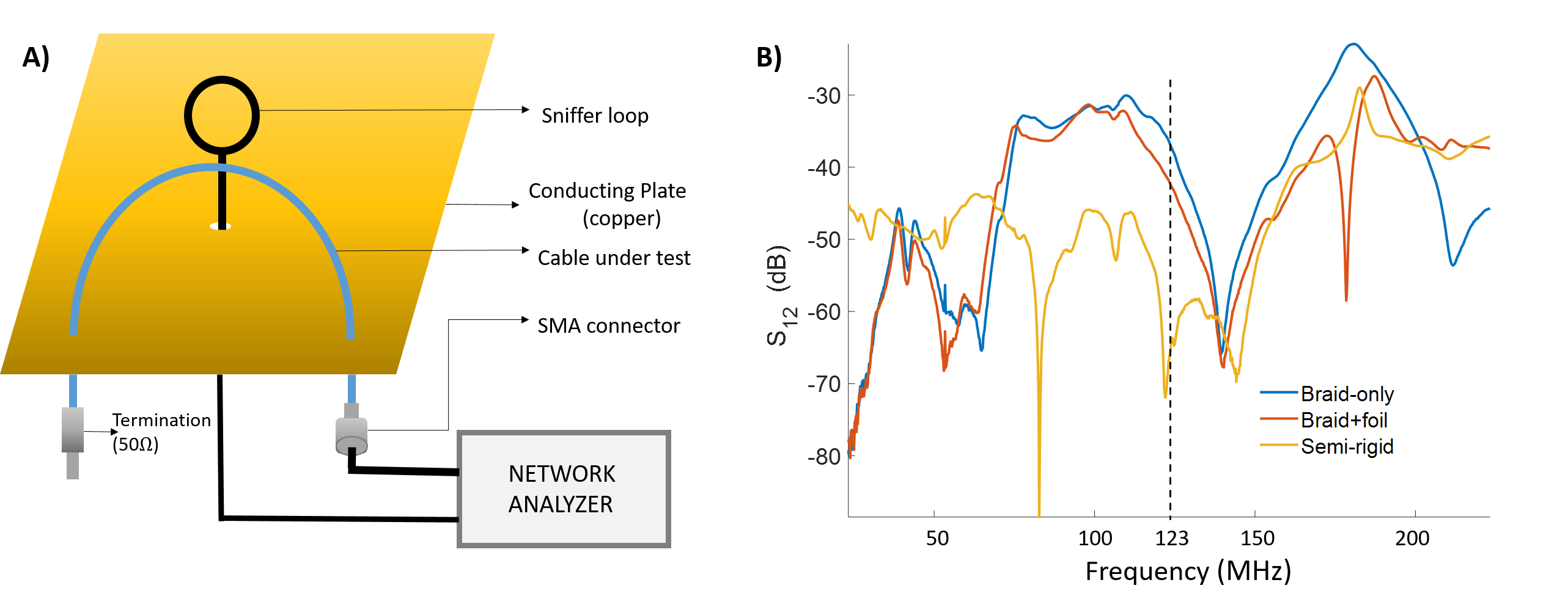
Fig. 1. Transfer impedance measurement setup for testing shielding effectiveness, which relates to higher surface currents (A). Transmission coefficient results for three different wires with braided-only, braiding and foil, and continuous shielding, i.e., semi-rigid. Shielding effectiveness is frequency-dependent. At the frequency of interest, 3T, SLRs constructed with semi-rigid cables are expected to perform superior to braided cables when the other wire parameters match.