2255
Construction and characterisation of a 7 Tesla flexible body coil with 10 transmit dipoles and 30 receive loops1Biomedical Engineering Department, School of Biomedical Engineering and Imaging Sciences, King's College London, London, United Kingdom, 2Centre for the Developing Brain, School of Biomedical Engineering and Imaging Sciences, King's College London, London, United Kingdom, 3Department of Cancer Imaging, School of Biomedical Engineering and Imaging Sciences, King's College London, London, United Kingdom
Synopsis
We present the first continuous 30-channel loop receive coil array combined with the 10-channel dipole parallel-transmit array for 7 Tesla body imaging. Array comprises a flexible anterior part with 6 dipoles and 18 loops, with 35cm longitudinal coverage along with a hard plastic posterior part containing 4 dipoles and 12 loops. Special features were added to help patient comfort and overcome cabling limitations. Simulations with computational human model show adequate B1+ coverage in areas of interest such as the prostate. Phantom images were taken showing promising results. Further development will follow, and human imaging is planned in the near future.
Introduction
The lack of body coils at 7 Tesla creates a need for dedicated transmit coils for each body area. However, due to the short wavelength at UHF, implementation of a large body coil is challenging and the use of volume coils such as the birdcage is not practical beyond the head area [1]. Transmit arrays consisting of loops are proposed with the use of RF shimming to target areas for imaging [2]. However, the penetration is inadequate when the ROI is deeper in the human body, such as the prostate [3-4]. Transmit dipoles overcome this problem since they can operate in the far field even when positioned near the skin, and they provide adequate coverage in deeper organs with RF shimming [5-6]. Moreover, a continuous loop receive array combined with local surface Tx coil array for 7T body imaging is lacking since decoupling of coil is very challenging in the conformal configuration [5-7]. The areas of interest targeted in this study were prostate, hip, and kidney.Methods
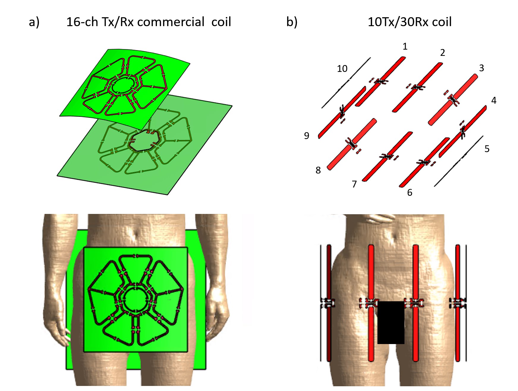
Requirements from our clinical team were for a 35cm head foot coverage and ability to image both more peripherally, to allow bilateral imaging of kidneys or hips without coil repositioning, and centrally for prostate. After an initial design study, ten 33cm long dipoles driven by the eight available channels and a 30-loop receive array made of square overlapped loops was selected. Design was evaluated with simulations and after construction, phantom imaging and measurements were acquired on a 7T MR scanner (MAGNETOM Terra, Siemens, Germany).Simulations: A FDTD software, Sim4Life (ZMT, Zurich), along with the Duke model from the virtual family [8] were used for B1+ and SAR evaluation. SAR efficiency B1+/√SAR maps and 10g averaging SAR maps were calculated for 2 shim cases, one in the prostate region and one for bilateral regions that would be used in the hip or kidneys. The same process was followed for a cardiac 16-loop transceiver coil made by RAPID biomedical (Germany) and used as a benchmark. CAD illustrations of both coils are provided in figure 1.
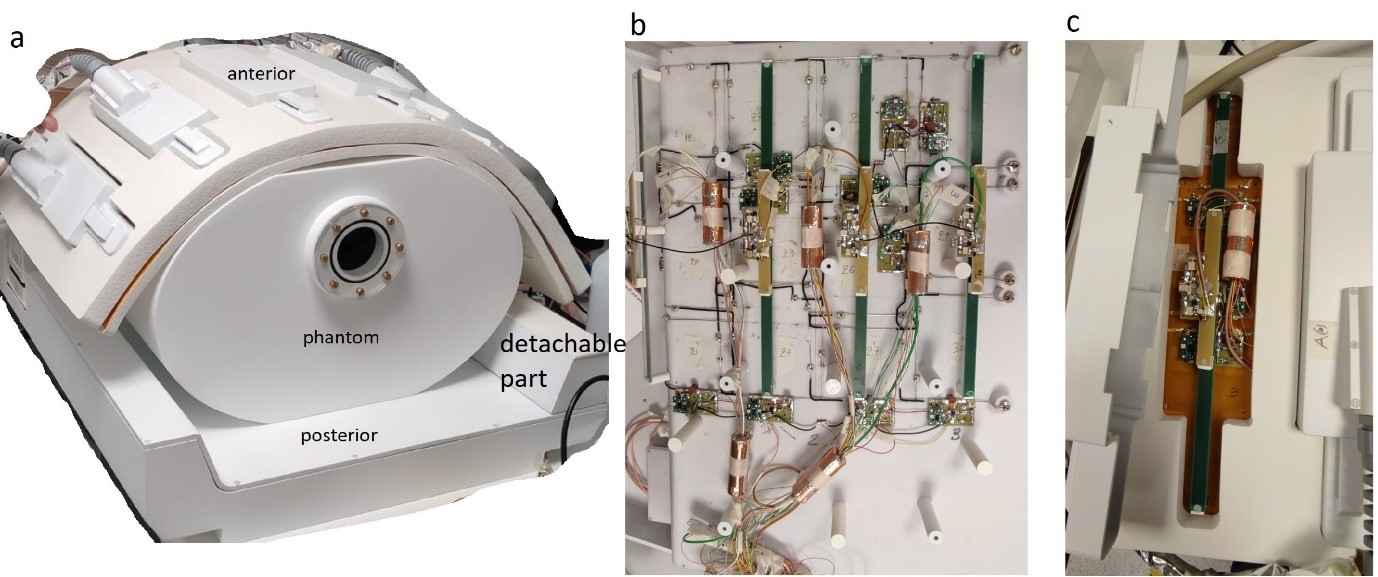
Construction: The coil comprises two parts, a posterior part with 4 Tx dipoles (33cm) and 12 Rx loops (12cmx12cm each) in a hard plastic enclosure, and an anterior part with 6 Tx dipoles and 18 Rx loops, which was designed to be flexible and follow the curve on the patient’s body. On one side of the posterior, a detachable part is used to extend the receive array and improve the left and right lateral coverage (figure 2). All parts were designed in CAD (SolidWorks, Dassault Systems, France), and 3D printed in polycarbonate (Deed3D, Guangzhou, China). PCBs were manufactured and populated with PIN diodes for active detuning, protection diodes for passive detuning, non-magnetic ceramic capacitors, RF chokes and fuses. Low input impedance LNAs were used for preamp decoupling. The 12 Rx loops in the posterior were made by silver copper wire with geometrical decoupling (figure 2). The 4 dipoles were placed 12mm below the receive loops level and floating BALUNs were used to guide the RF and DC cables (figure 2). Silicone sponge foam sheets were provided by PAR Group (UK) for the flexible part. The receive loops in the anterior were etched in a thin flexible laminate PCB manufactured by Beta-layout (Ireland). Layout included 18 loops of 3 different sizes to ensure neighbouring ones were geometrically decoupled. Finally, a 35-litre phantom was designed, 3D printed and was filled with a 4% NaCl solution (figure 2).
Results
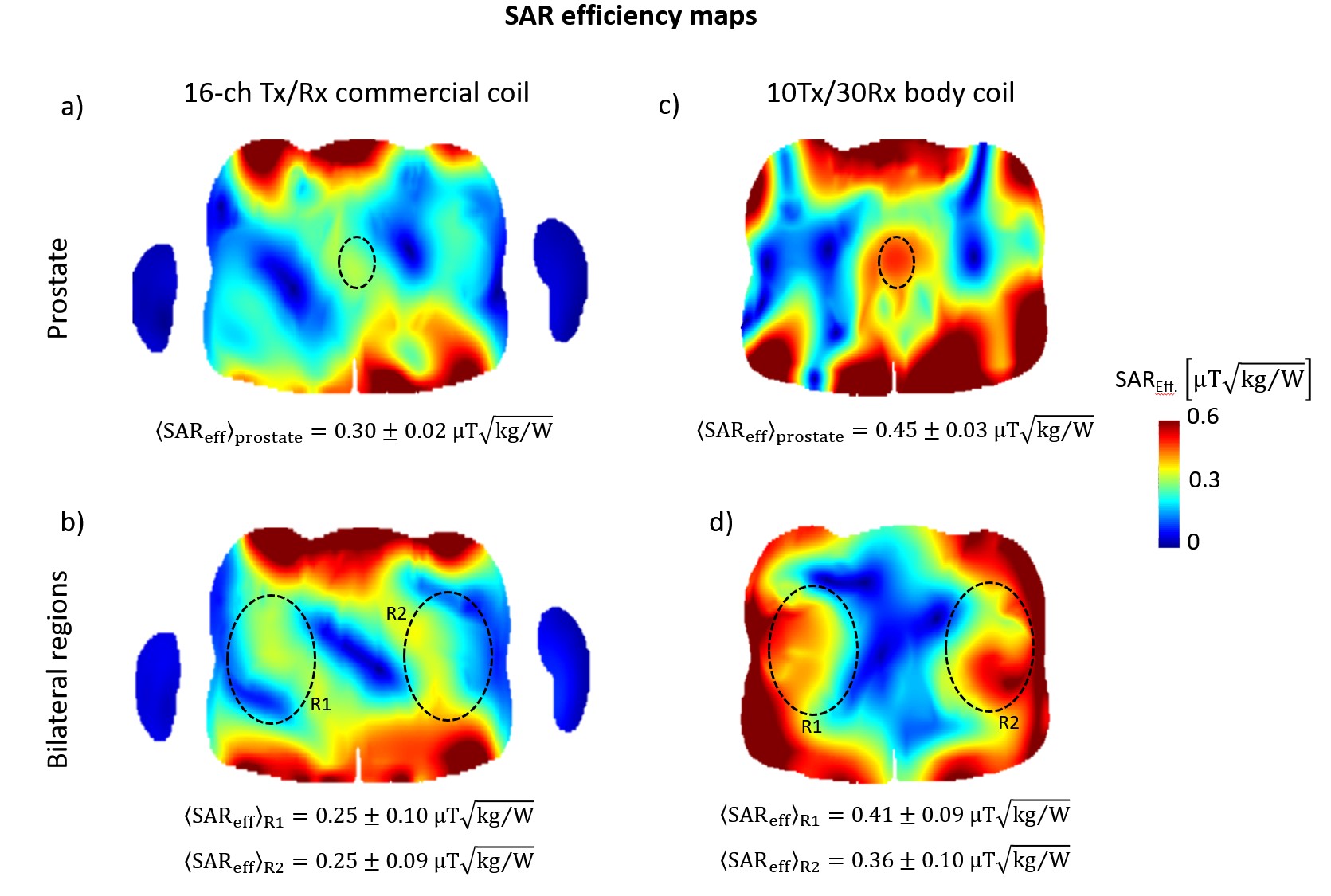
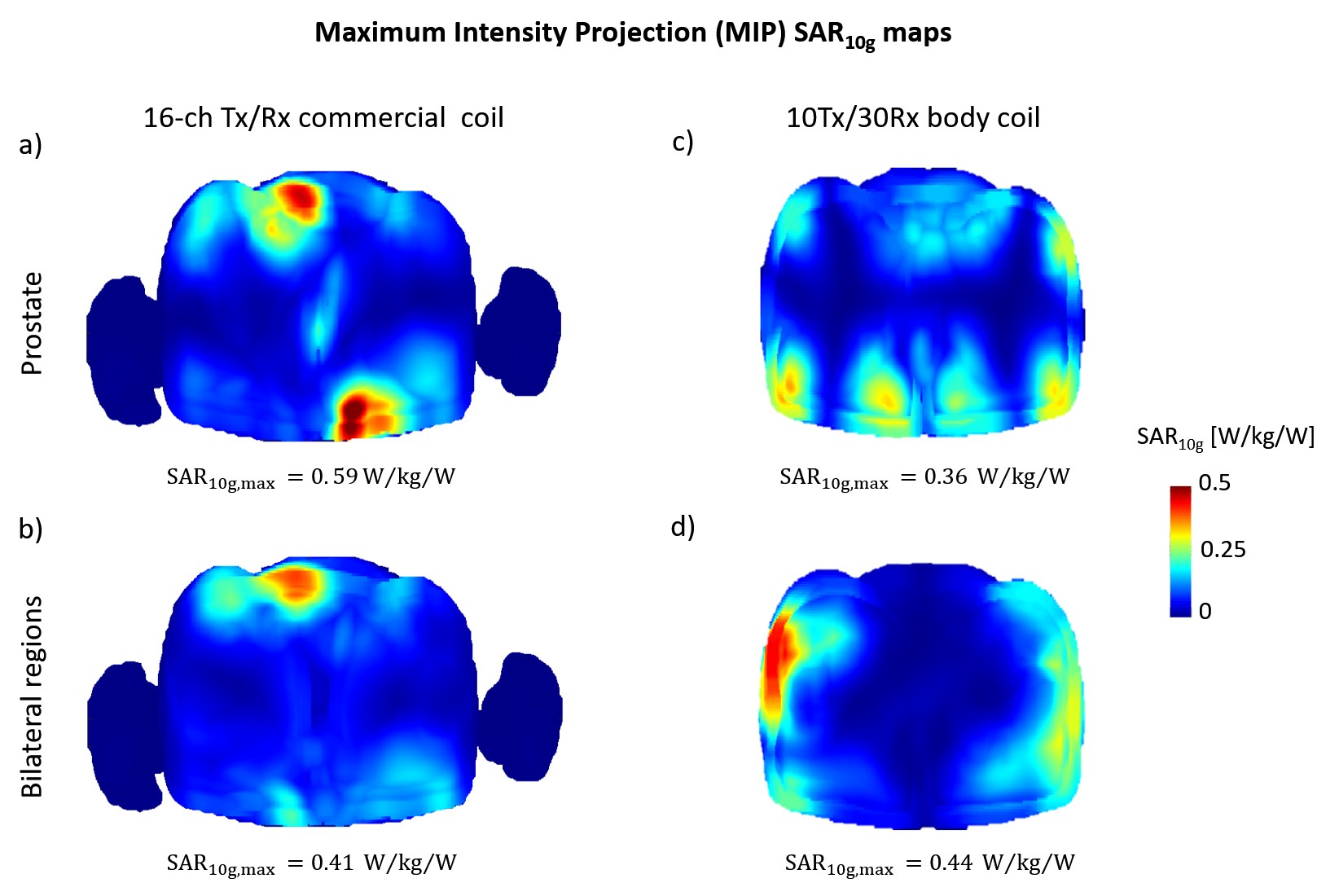
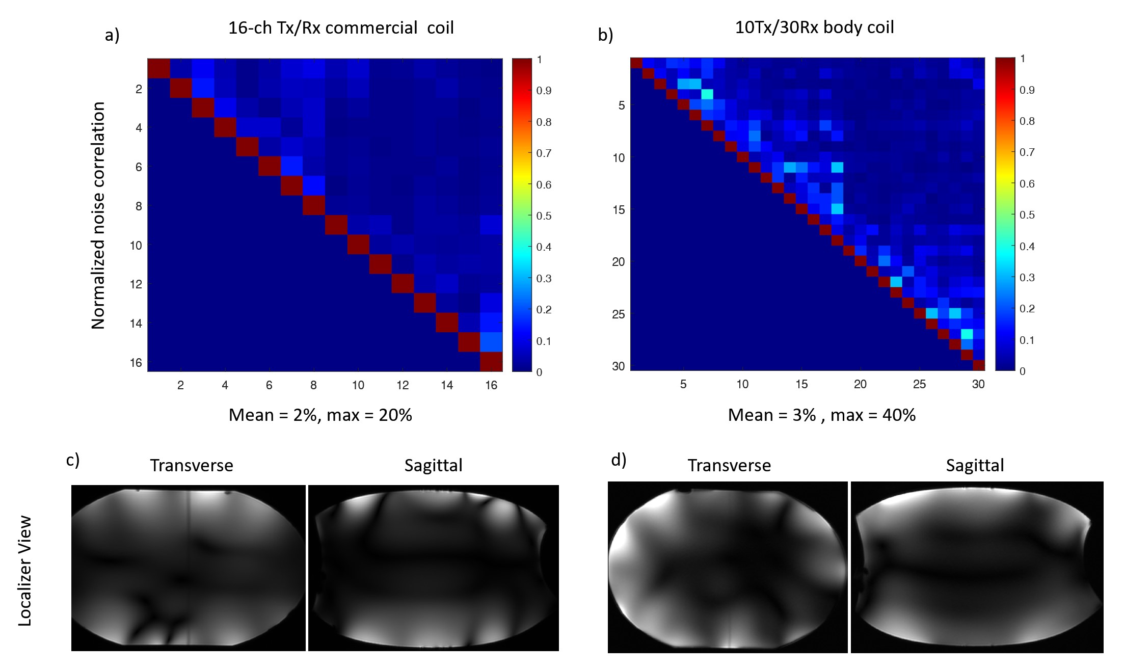
Results are summarised in the figures 3 and 4 for simulations and figure 5 for measurements in the scanner. SAR efficiency in the prostate and bilateral areas for the commercial coil averaged at 0.25 and 0.30 respectively. The 10Tx coil was on average 50% more efficient averaging 0.45 and 0.38 in the same areas. Max 10g SAR for the two shims were 0.59 and 0.41 (W/kg)/W for the commercial and 0.36 and 0.44 (W/kg)/W for the 10Tx coil. Thus, 10Tx coil gave on average 20% less SAR for 1W power input in the two RF shim scenarios. Noise correlation for the commercial coil was on average 2% while it was 3% for the 10Tx coil. Localizer images show the round coverage of the phantom compared to the top/bottom only in the commercial coil (figure 5).Discussion and Conclusion
A novel coil design is proposed holding both transmit dipoles and a receive array in one flexible assembly along with a rigid posterior part. Other flexible coil assemblies so far have had separate compartments for the Tx and Rx arrays but here they are embedded. Thus, superior coverage and ease of use is achieved. Dipole loading is well controlled since the distance from the skin is fixed due to the flexibility of the assembly. First results also work as a proof of principle that the two arrays can work in such proximity. Results were comparable to the commercial coil which had a limited B1+ coverage and the 10Tx coil was superior in its B1+ vs SAR performance for both prostate and bilateral shims by a 50% margin. After the required approval process, human imaging will be performed for further evaluation.Acknowledgements
This work was supported by King’s Health Partners Grant (MRC, 2020-2021) and core funding from the Wellcome/EPSRC Centre for Medical Engineering [WT203148/Z/16/Z], the Wellcome Trust Collaboration in Science grant [WT201526/Z/16/Z], and by the National Institute for Health Research (NIHR) Biomedical Research Centre based at Guy’s and St Thomas’ NHS Foundation Trust and King’s College London and/or the NIHR Clinical Research Facility. The views expressed are those of the author(s) and not necessarily those of the NHS, the NIHR or the Department of Health and Social Care.References
[1] Erturk MA, Li X, Van de Moortele PF, Ugurbil K, Metzger GJ. Evolution of UHF Body Imaging in the Human Torso at 7T: Technology, Applications, and Future Directions. Top Magn Reson Imaging. 2019 Jun;28(3):101-124.
[2] Mao W, Smith MB, Collins CM. Exploring the limits of RF shimming for high-field MRI of the human head. Magn Reson Med. 2006 Oct;56(4):918-22.
[3] Ipek O. Raaijmakers AJE., Klomp DWJ., Lagendijk JJW., Luijten PR., van den Berg CAT. Characterization of transceiver surface element designs for 7 tesla magnetic resonance imaging of the prostate: radiative antenna and microstrip. Phys Med Biol 20212 57 343.
[4] Lattanzi R, Wiggins GC, Zhang B, Duan Q, Brown R, Sodickson DK. Approaching ultimate intrinsic signal-to-noise ratio with loop and dipole antennas. Magn Reson Med. 2018 Mar;79(3):1789-1803.
[5] Erturk MA., Raaijmakers AJE., Adriany G., Ugurbil K., Metzger GJ. A 16-channel combined loop-dipole transceiver array for 7 Tesla Body MRI. Magn Reson Med 2017; 77:884-894.
[6] Steensma BR, Voogt IJ, Leiner T, Luijten PR, Habets J, Klomp DWJ, van den Berg CAT, Raaijmakers AJE. An 8-channel Tx/Rx dipole array combined with 16 Rx loops for high-resolution functional cardiac imaging at 7 T. MAGMA. 2018 Feb;31(1):7-18.
[7] Rietsch SH., Orzada S., Maderwald S., Brunheim S., Philips BWJ., Scheenen TWJ., Ladd ME., Quick HH. 7T ultra-high field body MR imaging with an 8-channel transmit/32-channel receive radiofrequency coil array. Medical Physics 2018.
[8] Gosselin M C, Neufeld E, Moser H, Huber E, Farcito S, Gerber L, Jedensjö M, Hilber I, Di Gennaro F, Lloyd B, Cherubini E, Szczerba D, Kainz W, Kuster N, Development of a new generation of high-resolution anatomical models for medical device evaluation: the Virtual Population 3.0, Physics in Medicine and Biology, 59(18):5287-5303, 2014.
Figures