2187
Coupling study between two concentric whole-body MRI birdcage coils: towards a whole-body X-nucleus coil1Department of Health Technology, Technical University of Denmark - DTU, Kgs. Lyngby, Denmark, 2Department of Electrical Engineering, Technical University of Denmark - DTU, Kgs. Lyngby, Denmark
Synopsis
The feasibility of integrating a whole-body X-nucleus birdcage in a wide-bore clinical 3T MR scanner is evaluated. The challenge is that this extension coil has to be tightly fit into the scanner bore, having a diameter just 16 mm smaller than the concentric 1H coil. Different configurations are proposed and evaluated with the purpose of minimizing interaction between the X-nucleus coil and the native 1H body coil of the scanner. Experimental results are in agreement with simulations and demonstrate a 1H coil detuning of 0.4 MHz due to co-integration with X-nucleus birdcage.
Introduction
MRSI has proven to be a powerful method to interrogate metabolic processes of the human body. However, the additional coil setups needed can reduce substantially the space available for the patient within the scanner bore. Additionally, for hyperpolarized MRI, the need for an homogeneous B1+ is higher than for 1H, since local maxima of B1+ field can saturate the hyperpolarized spins and waste polarization1.A more convenient and practical solution would be to have a whole-body X-nucleus coil integrated into the scanner bore. A 70 cm double-tuned 1H-13C body coil has already been proposed2 for a clinical scanner, based on a 4-ring birdcage design3. Here we explore an alternative approach: to insert a secondary whole-body coil, coexisting with the native 1H coil of the scanner. This approach has the advantage of allowing the secondary coil to be removed, if necessary. Thus, this solution allows for a setup where there could be several interchangeable body coils (for different nuclei), which can be installed and removed when necessary.
In this work, the coil design requirements are evaluated, in order to maintain the tuning of the 1H coil undisturbed. Several options to minimize capacitive and inductive coupling are studied. The B1+ efficiency is investigated for the case of 13C at 3T (32.1 MHz), which is the target nuclei in the present application (the rest of the study is valid for any other nuclei). Finally, a prototype of the most favorable design was fabricated, and a bench characterization made to confirm the simulated results.
Materials and Methods
Simulation StudyAn EM simulation of the 1H coil, including the scanner RF shield, was conducted using CST (Darmstad, Germany), with the dimensions of a clinical 3T system (70 cm bore). The 3D EM model of the 1H coil is shown in Fig. 1, together with the fabricated mockup. The X-nucleus coil has a length of 592 [mm], 16 legs, and a diameter such that can be integrated into the scanner bore, between the bore and the bed (Ø = 687 [mm]).
The capacitive coupling between the coils was evaluated for three different geometries of the conductive structure of the secondary coil: using a) 25 mm, b) 100 mm wide copper sheet, and c) copper wire (Ø=3.6 mm). For these simulations, 48 air gaps were added to the X-nucleus coil, to avoid inductive coupling (one gap in the center of each leg, and one gap in each of the 16 segments of the end-rings). A zoom into the 3D models is shown in Fig 2.a).
A parametric simulation was performed to determine the level of blocking impedance at the 1H frequency needed in each of the 48 gaps, to provide sufficient current suppression. Finally, the effect of the 1H trap losses on the B1+ efficiency of the secondary coil was evaluated using realistic values for the lumped elements. This part of the study was done for 13C at 3T (32.1 MHz).
Experimental Validation
A prototype of the X-nucleus coil, made out of copper wire (Ø=3.6 mm) was fabricated, as shown in Fig. 5.a). The S11 of the 1H coil was measured with the presence of the secondary coil, for a different number of air gaps (24, 32 and 48). For the setup with lower mutual coupling (48 gaps), the frequency response of the S12 between the 1H coil and a pickup loop was measured.
Results and Discussion
Fig. 2 shows the effect of the capacitive coupling between the coils, where substantial detuning of the 1H coil is observed. Based on this result, the X-nucleus coil made of copper wire was used for the rest of the study. Fig 3.a) shows how the level of blocking impedance of the 1H traps impacts the S11 of the 1H coil. A blocking impedance of 5 kΩ (for each trap) is deemed necessary to minimize inductive coupling. Fig 3.c) shows the blocking impedance (at the 1H frequency) of an LCC filter, implemented using realistic loss for its lumped elements. To achieve the needed blocking impedance, an inductor above 70 nH is needed for the LCC traps.Fig. 4 shows the 13C B1+ efficiency reduction due to the insertion of the LCC traps, which is about 12% lower at the coil center (compared to the coil without LCC traps). Finally, the measured |S11 | of the 1H coil is shown in Fig 5. When the secondary coil has 48 gaps, the frequency detuning of the 1H coil is 0.4 MHz. This result agrees well with the simulation (blue curve in Fig 2.c)). A zoomed-in detail of the effect over the transmitted signal to a pickup loop, shows a reduction of 0.9 dB of the |S12 | at the 1H frequency.
Conclusion
The feasibility of integrating a whole-body X-nucleus coil into a clinical MR system has been studied, where the primary challenge was to make it compatible with the native 1H body coil of the scanner. Such double-coil setup allows for the removal and replacement of the secondary coil, such that the MR scanner can always be reconfigured to its original state. This solution has the advantage that can be added to any MRI scanner that is already in operation.Acknowledgements
No acknowledgement found.References
1. Harlan CJ, Xu Z, Walker CM, Michel KA, Reed GD, Bankson JA. The effect of transmit B1 inhomogeneity on hyperpolarized [1‐13C]‐pyruvate metabolic MR imaging biomarkers. Med Phys. 2021;48(9):4900-4908. doi:10.1002/mp.15107.
2. Boskamp E, Xie Z, Taracila V, et al. A dual-tuned 70cm whole-body resonator for 13C and proton MRI/MRS at 3T. In: Poster Presented at: Joint Annual Meeting ISMRM-ESMRMB. Vol 1714. ; 2018.
3. Murphy-Boesch J, Srinivasan R, Carvajal L, Brown TR. Two Configurations of the Four-Ring Birdcage Coil for 1H Imaging and 1H-Decoupled 31P Spectroscopy of the Human Head. J Magn Reson Ser B. 1994;103(2):103-114. doi:10.1006/jmrb.1994.1017.
Figures
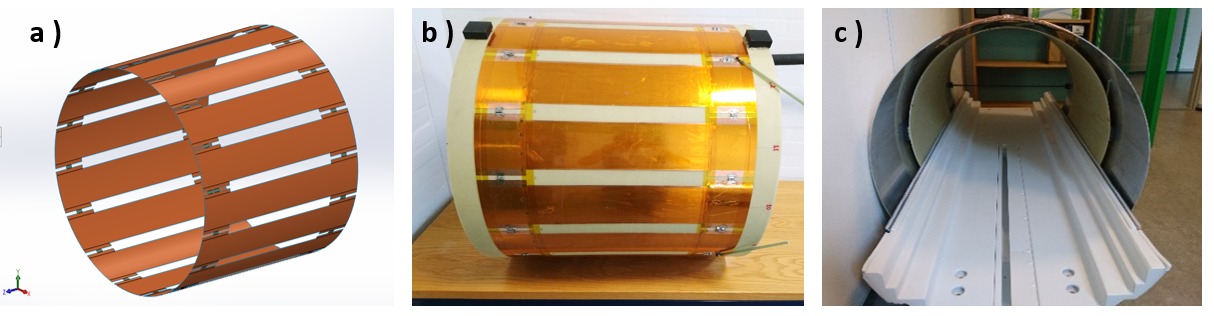
Figure 1. A) Simulation model of the 1H whole-body birdcage coil. B) Fabricated coil, using copper sheet (100 mm wide, 70 μm thick), placed over a fiberglass cylinder. C) Full setup, including the 1H body coil, the RF shield, and the rail system of the scanner bed. The bore inner diameter is 695 [mm]. The coil is tuned to 127.73 MHz.
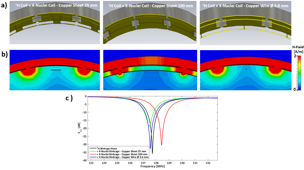
Figure 2. EM simulations of the complete setup, including different versions of the X-nucleus coil, to evaluate the interaction between coils due to capacitive coupling. A) Detail of the simulated models of the concentric 1H and X-nucleus coils. B) Detail of the H-field distribution (per Watt) between the legs of the two coils. C) Simulated |S11 | of the 1H coil, alone and in combination with the different X-nucleus coil models.
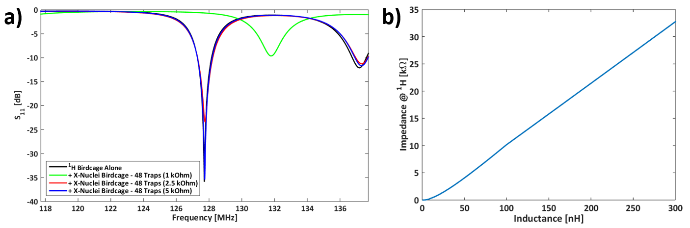
Figure 3. A) Simulated |S11 | of the 1H coil, alone and in combination with the X-nucleus coil made of 3.6 mm thick copper wire, for different values of blocking impedance of the 1H traps. B) Calculated blocking impedance of an LCC trap, taking in account the realistic value for the lumped element inductor (Q=140).
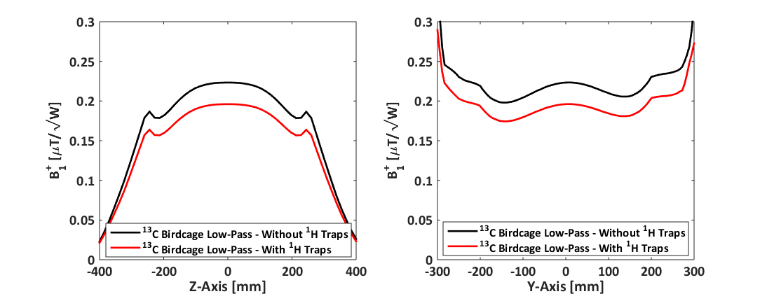
Figure 4. Simulated B1+ (per Watt) across the central axis of the axial (XY) and sagittal (XZ) planes of the whole-body 16-leg low-pass birdcage, tuned to the frequency of 13C at 3T (32.1 MHz). The effect of adding the losses of the 1H traps is shown by the red line, with an efficiency reduction at the center of 12% when adding 48 1H traps (0.223 vs. 0.196 [μT/√W]).
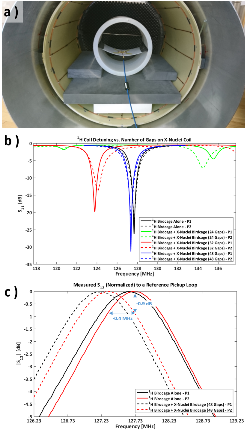
Figure 5. A) Setup for the experimental validation of the interaction between the 1H birdcage and the conductive structure of the 16-leg X-nucleus birdcage. B) Measured detuning of the 1H birdcage, for different number of gaps on the X-nucleus birdcage. C) Effect of the detuning on the measured |S12 | between the 1H birdcage and a pickup loop placed at the center of the coil. P1 and P2 denote the two quadrature ports of the 1H coil (0° and 90° respectively).