2186
2nd-order meander dipoles for 7T head coil passive RF shimming1Aix Marseille Univ, CNRS, CRMBM, Marseille, France, 2Aix Marseille Univ, CNRS, Centrale Marseille, Institut Fresnel, Marseille, France, 3Multiwave Imaging, Marseille, France, 4CEA, DRF/Joliot/Neurospin, Université Paris-Saclay & CNRS, Gif-sur-Yvette Cedex, France
Synopsis
Active and passive RF shimming approaches have been proposed to diminish the B1+ inhomogeneities commonly found in a birdcage coil at 7T. In a previous work, we have introduced a meander dipole based on two 3rd-order Hilbert fractals as an alternative solution for passive shimming. In this work we optimized their design using six 2nd-order Hilbert fractals. Simulations and in vivo MRI at 7T using these structures showed strong B1+ enhancement in the area between the two meander dipoles whereas B1+ was reduced in regions below and above the fractal pads.
Introduction
Due to the well-known wavelength reduction at 7T, birdcage head coils suffer from B1+ inhomogeneities that translate to higher signal at the center of the image and lower signal in the area close to the coil. As a simpler alternative to active B1+ shimming (pTx1,2), passive RF shimming approaches were proposed using passive elements such as dielectric pads3-5 and metamaterials6,7 to control B1+ within the head coils. We previously proposed a meander dipole (MD) based on two 3rd-order Hilbert fractals connected in series as a promising shimming solution8. Although they enhanced B1+ in the region of interest, the effect was very local and moderate in amplitude. In this work, we present a new design of meander dipole based on six 2nd-order Hilbert fractals connected in series to improve on these limitations. The new meander dipoles were numerically studied and experimentally tested in vivo.Material and Methods
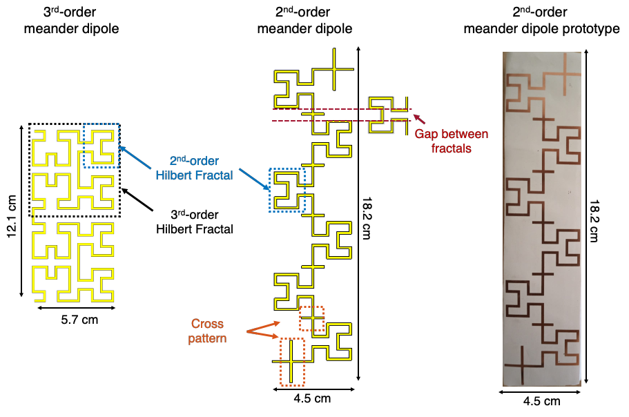
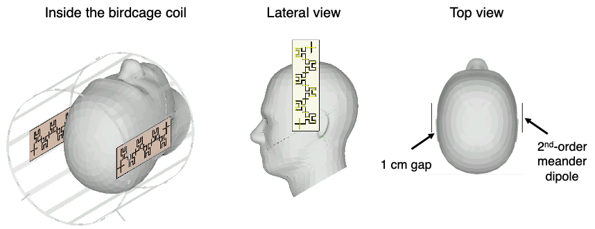
Six 2nd-order Hilbert fractal metallic strips connected in series were designed (Figure 1). A cross pattern was added between the fractals to decrease their quality factor. The copper structures were simulated in a 16-leg birdcage coil and in presence of a homogeneous anthropomorphic phantom of permittivity ɛ= 45.3 and conductivity σ= 0.87 S/m. Their effect on B1+ was compared with that of the 3rd-order MDs proposed earlier. They were printed on a 0.5-mm-thick Rogers 3003 substrate and tested in vivo in a Tx/Rx proton head coil (Invivo Corp., Gainesville, FL) in a 7T Magnetom MRI scanner (Siemens Healthineers, Erlangen, Germany) on one healthy volunteer. Informed consent was obtained from the volunteer prior the scan. Two MDs were placed at 1 cm distance on both lateral sides of the head (Figure 2). We measured B1+ maps using the XFL MRI sequence9 ( TR=20s, TE=3.06ms, FA=4°, Shinnar-Leroux-minimum-phase-saturation-pulse=60°, FOV=256mm, matrix=64x64 and 3 slices of thickness=4mm). One central slice was acquired in each of the three main orientations. Three GRE image slices were acquired with the same geometry (parameters TR=20s, TE=3.06ms, FA=3°, FOV=256mm, matrix=128x128, slice thickness=4mm). All images were acquired using the same reference voltage of 260V.Results
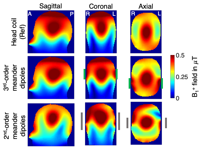
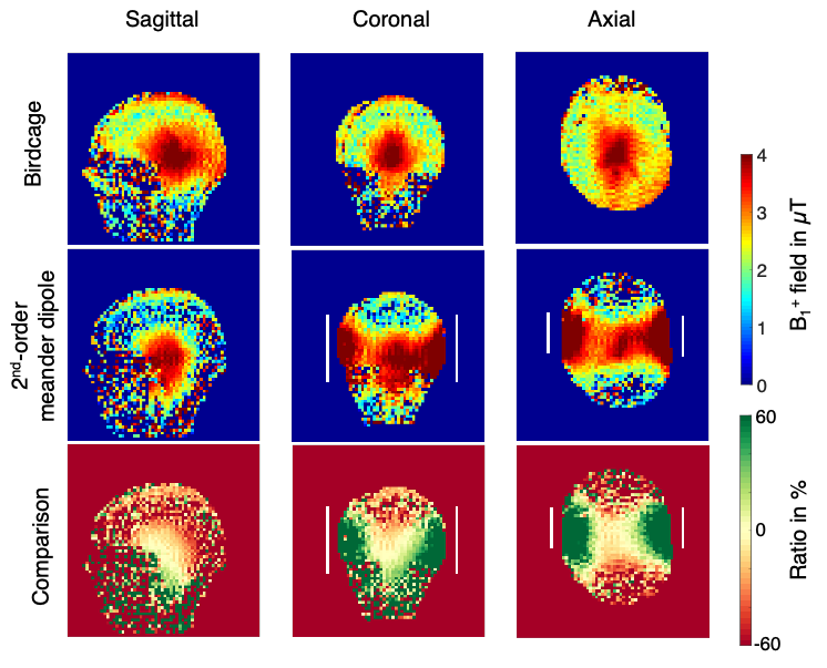
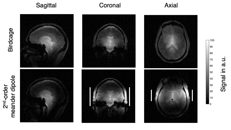
Figure 3 shows the numerical B1+ maps with the birdcage coil alone (top), with the earlier proposed 3rd-order MDs (center) and with the 2nd-order MDs (bottom). The 2nd-order MDs (gray rectangles) produced a stronger B1+ enhancement in the temporal lobes than the 3rd-order MDs (green rectangles), visible in the coronal and axial slices. However, the B1+ gain in this region was paired with strong losses in other regions. A comparable field distribution was confirmed by the B1+ maps measured in vivo (Figure 4). The third row shows the relative B1+ change when compared with the reference. The field was enhanced by about 60% in the temporal region close to the MDs (white rectangles), unchanged in the center and reduced by about 60% in frontal, posterior and top regions.The in vivo GRE images show a similar distribution (Figure 5) with an almost complete signal loss in certain regions.Discussion
The 3rd-order Hilbert fractal design proposed earlier allowed us to produce compact structures, which, however, compromised the effect of the MD as a secondary B1+ field source. To regain the effect, we required a more elongated structure which was obtained with the 2nd-order Hilbert fractals. The resulting structures had the double length (18.2 cm) but were much shorter than a straight electric dipole used for 7T applications (approx. 40 cm). The chosen substrate made it possible to obtain thin, compact, and flexible resonant structures. By adding the cross pattern, we were able to decrease the quality factor. The obtained meander dipoles showed a 60% higher B1+ in the area between them, (Figure 4), doubling the gain achieved with the earlier-proposed 3rd-order meander dipoles8. Nevertheless, the new structures also led to strong B1+ reductions in other regions, which was not the case for the former (Figure 3). Complete loss of GRE image signal was observed in anterior, posterior, and top regions of the brain (Figure 5), similar to other RF shimming solutions6,7. The 2nd-order meander dipoles could therefore be seen as spatial lenses, focusing the field on a specific region.Conclusion
We proposed a new design of meander dipoles based on composite 2nd-order Hilbert fractals with the aim of reducing B1+ inhomogeneities present in a 7T birdcage coil. Thanks to their compact and flexible design they were easy to handle and could be placed between the head and the RF coil. These passive elements were able to increase the B1+ field by up to 60% in the temporal lobes. However, strong signal loss was observed in other regions. Further studies and optimization of these structures are required to reach the initial goal of enhancing multiple regions without losing efficiency of the coil in other areas.Acknowledgements
This project has received funding from the European Union's Horizon 2020 research and innovation programme under grant agreement No 736937 first (M-CUBE project), and then under grant agreement No 952106 (M-ONE project), and from the Excellence Initiative of Aix-Marseille University - A*MIDEX, a french "Investissements d'Avenir" programme under Multiwave chair of Medical Imaging.References
[1] Shajan, et al., 2011, Magnetic resonance in medicine, 66(2), 594-602
[2] Wald, et al., 2009, Magnetom Flash, 40(1)
[3] Webb, 2011, Concepts Magn. Reson. Part A 38A, 148
[4] O’Reilly, et al., 2016, J. Magn. Reson. 270, 108-114
[5] Neves, et al., 2018, Magn. Reson. Med. 79, 1753
[6] M. Dubois, et al., 2018, Phys. Rev. X 8, 031083
[7] M. Dubois, et al., 2019, Proc. Intl. Soc. Mag. Reson. Med. 27, 1552
[8] Vergara, et al., 2020, Proc. Intl. Soc. Mag. Reson. Med. 28.
[9] Amadon A., et al., 2015, Proc. Intl. Soc. Mag. Reson. Med., 23, 2377
Figures