2185
Hybrid 3T 8-channel Receive Array Using a Metamaterial Slab and Companion Loop Elements: Comparison to a Conventional Array1Electrical and Computer Engineering, University of Alberta, Edmonton, AB, Canada, 2Oncology, University of Alberta, Edmonton, AB, Canada, 3Medical Physics, Cross Cancer Institute, Edmonton, AB, Canada
Synopsis
Metamaterials (MTMs) have been used as passive elements to improve the receive sensitivity in MRI by enhancing the field locally, but not connected directly as receive elements. We present the design and construction of a novel 2D transmission line based MTM employed as a 4-port element combined with an additional 4-element coil array. Simulation and measurement of receive sensitivity are compared to those of a conventional 8-element coil array covering the same region. The receive sensitivity in a human torso sized phantom is found to be equivalent, while the MTM slab additionally enhances the transmit performance.
Introduction
Metamaterials (MTMs) have been used to enhance the field distribution and magnitude of both transmit and receive resonators in MRI, but they occupy more space than local transmit or receive elements at the same location1,2. Additionally, the effects on the transmit field are not always desirable or controllable, and can negatively affect the overall transmit field homogeneity or specific absorption rate (SAR)3. We propose a slab of MTM based on 2D transmission lines. Unlike previous implementations of MTMs in MRI, it is employed as part of a receive array, with four ports connected to the slab. In transmit, the MTM slab provides benefits of improved efficiency, homogeneity and SAR as described in our companion abstract5. In receive, the slab provides the benefits of higher signal-to-noise (SNR) with large field-of-view (FOV), without requiring additional space over that required for passive transmit shimming.Methods
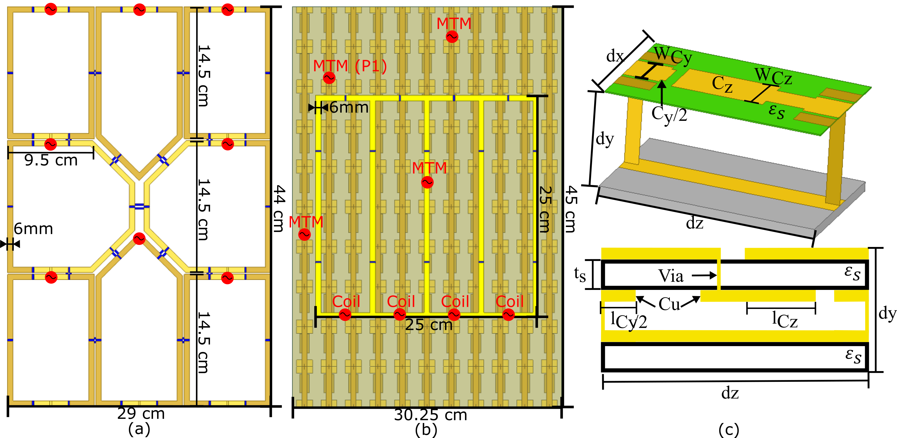
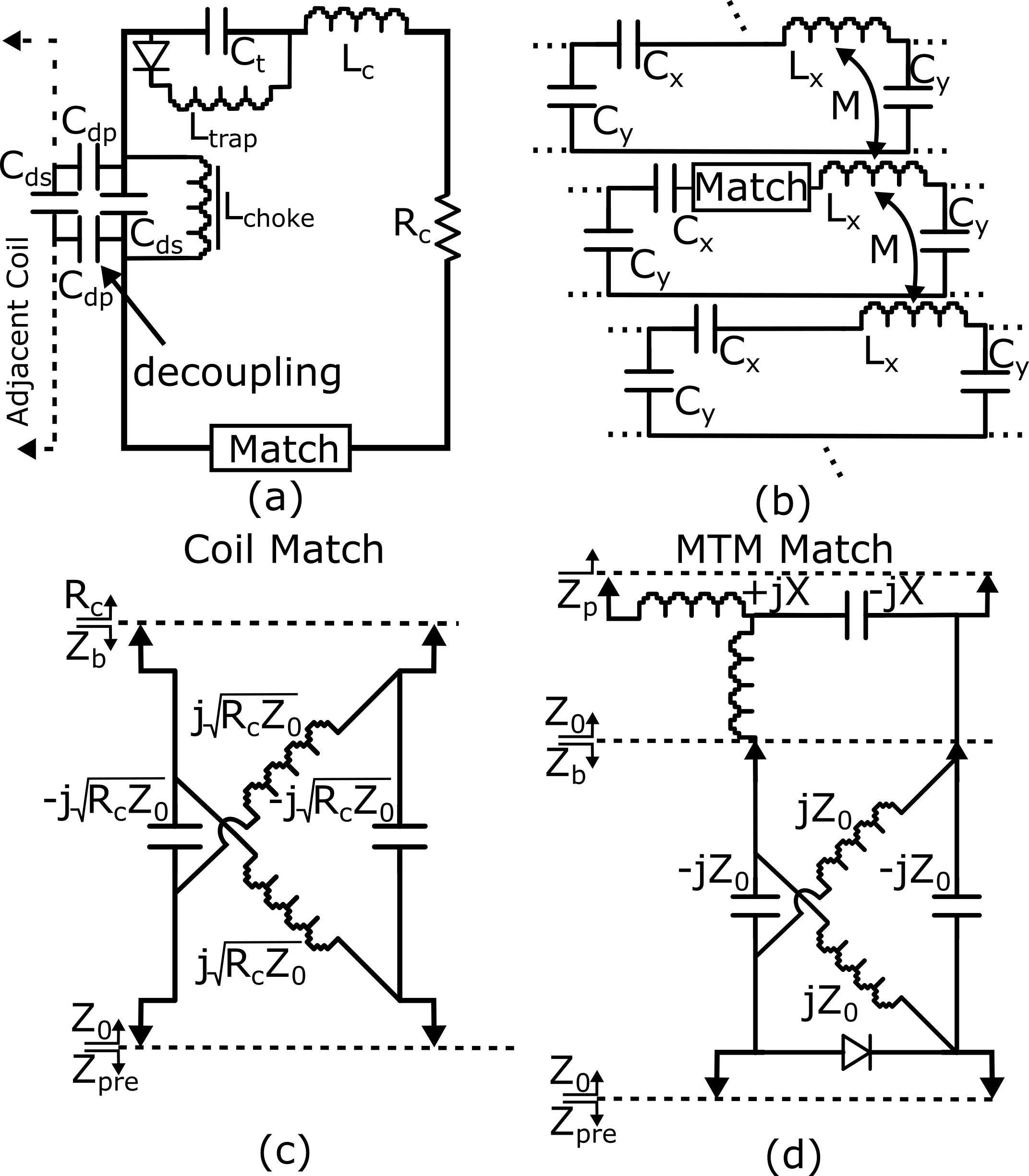
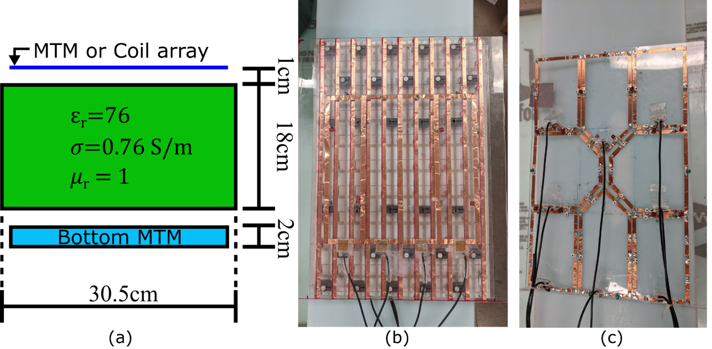
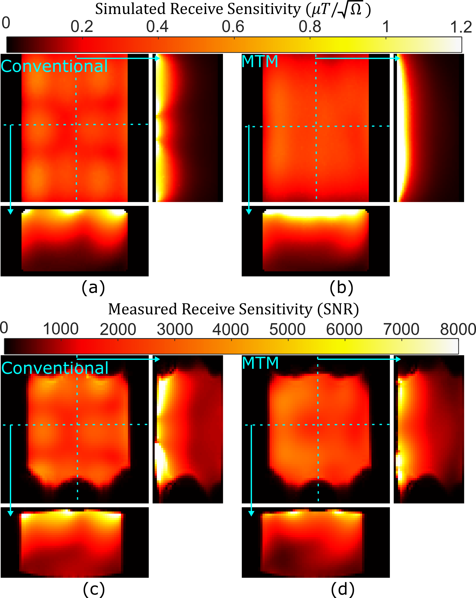
The receive arrays cover a volume the size of the human thorax/abdomen. The conventional array (Figure 1(a)) was designed without overlap with capacitive decoupling between adjacent elements5 (Figure 2(a)). The simulation model of the metamaterial slab and companion 4-element receive array are shown in Figure 1(b); the adjacent elements in the ladder network are decoupled by capacitors placed in series with the shared section of conductor. The MTM slab consists of 1D transmission lines broadside-coupled by mutual impedance to adjacent lines, as illustrated in Figure 2(b). It was tuned for a one-λ resonance in both directions, as described in reference (6), so its ports are naturally decoupled from each other as well as from the loop elements. This resonance also ensures that the MTM slab ports are naturally decoupled from the birdcage coil at the Larmor frequency. The geometry is illustrated in Figure 1(c) along with the various geometric tuning parameters of the MTM slab. The capacitive tuning elements consist of overlapping copper strips (18μ m thick) on thin ROGERS 3006TM substrate (0.25mm thick, ε =6.15, tanδ =0.002), while a bottom 2mm thick polycarbonate substrate provides mechanical support along with PVC structural blocks and nylon screws. Conventional preamplifier decoupling via a lattice balun matching network is performed as shown in Figure2(c). For the MTM slab ports, an additional network is required, where the blocking impedance of the lattice balun (Zb) during transmit results in a small impedance. The enhancement of transmit performance is thus unaffected by the ports. In simulation (Ansys, HFSS), the copper is modeled with a conductivity of 5.8$$$×10^7$$$S/m. The simulated field ($$$B ̂_1^-$$$) was used to calculate the intrinsic SNR in a phantom (Figure 3(a)), with the fields produced by the elements of the Rx array combined as in reference (7). The receive sensitivity was measured with the combined MTM slab and 4-element companion array (Figure 3(b)), as well as with the conventional 8-element array (figure 3(c)). Flip angle (FA) was mapped by varying the prescribed FA (50°, 100° and 150°) using a 2D multi-slice SPGR sequence and least squares fitting pixelwise to the SPGR equation9 (500Hz/pixel, 70×70×33 matrix, 6×6×6mm3, TE=2.6ms, TR=800ms) in a phantom (3.6 g/L NaCl and 1.96 g/L CuSO4⋅5H2O aqueous solution8) matching the simulation permittivity and conductivity. The receive sensitivity is reported as the SNR obtained with a 90° FA.Results and Discussion
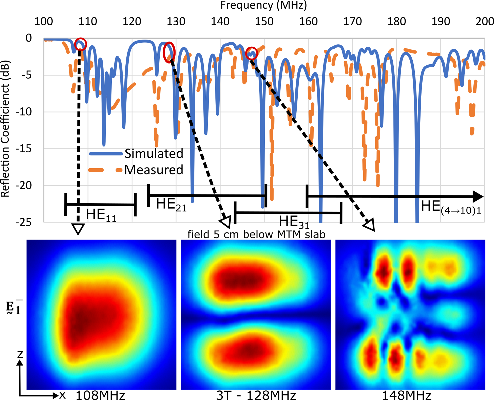
The simulated and measured reflection coefficient prior to matching is shown in Figure 4 for a port of the MTM slab. Direct match between the separation and position of modes in measurement and simulation is not expected due to variations in construction. Tuning is performed so at the 3T frequency (128MHz) the same resonant mode is achieved. The mode profile of the slab is analogous to that of a corrugated, or leaky-wave, rectangular waveguide, so the frequency range over which hybrid-electric (HE) modes occur is indicated. The field profile at three frequencies, (including 128MHz), is shown. The central null in the MTM slab sensitivity is compensated for by the companion loops. If tuned directly for the HE11 resonance, the slab would interact strongly with the volume transmit coil and companion coils, while if tuned for a higher mode order mixing of multiple modes would result in low sensitivity. The simulated receive sensitivity of the conventional array is shown in Figure 5(a) and in Figure 5(b) for the MTM slab and 4-loop combination. The receive sensitivity of both setups is similar in the three orthogonal planes, with a highly homogeneous field profile in the coronal slice observed with the MTM and 4-loop combination. A qualitatively similar measured receive sensitivity distribution is achieved for both setups (Figure 5(c) and Figure 5(d)). Because of limited gradient linearity the full longitudinal extent cannot be observed, and in the central region the middle elements of the 4-loop array currently have lower sensitivity than predicted by simulation.Conclusion
In transmit, the MTM slabs were found to improve the mean transmit efficiency by 39%, improve homogeneity and reduce the specific absorption rate. Combined with a receive sensitivity that is equivalent to a conventional receive array occupying the same space and with the same number of elements, these results motivate the use of MTMs in combination with conventional elements to improve overall imaging performance at 3T.Acknowledgements
This work was supported by the Alberta Innovates postdoctoral fellowship in health innovation, a studentship from the Office of the Provost and VP of the University of Alberta, and research grants from the Natural Sciencesand Engineering Research Council (NSERC) of Canada Discovery Grants program. We thank CMC Microsystems for software access and support by the University of Alberta Faculty of Engineering IT. The Cross Cancer Institutemachine shop provided support manufacturing structural elements of the MTM. We thank Philips Healthcare for training (AMM) and technical support, and Dr. R. Luechinger for the PATI program used to transfer data.References
1. Merkle EM, Dale BM. Abdominal MRI at 3.0 T: The Basics Revisited American Journal of Roentgenology (2006) 186(6):1524-1532
2. Brink WM, van den Brink JS, Webb AG. The effect of high-permittivity pads on specific absorption rate in radiofrequency-shimmed dual-transmit cardiovascular magnetic resonance at 3T. J Cardiovasc Magn Reson. (2015) 17(1):82
3. Brink WM, Gulani V, Webb AG, Clinical applications of dual-channel transmit MRI: A review. J. Magn. Reson. Imaging, (2015) 42: 855-869
4. Gomez TSV, Dubois M, Jomin P, Benamara M, Berrahou D, Georget E, Antonakakis T, Bendahan D, Kober F, Enoch S, and Abdeddaim R. Lightweight Metasurface Pads for Passive RF Shimming in 3T Abdominal Imaging Proc. Intl. Soc. Mag. Reson. Med. (2021) 29:1405
5. Vorobyev,V, Shchelokova A, Efimtcev A, et al. Improving Homogeneity in Abdominal Imaging at 3T with Light, Flexible, and Compact Metasurface. Magn Reson Med. (2021)
6. Maunder A, De Zanche N, Iyer AK. "Design and Modelling of Metamaterial Resonators for 3 Tesla Magnetic Resonance Imaging," 2021 International Applied Computational Electromagnetics Society Symposium (ACES) (2021)
7. Maunder A, Iyer AK and De Zanche N. Hybrid 3T 8-channel Array Using a Metamaterial Slab and Companion Loop Elements: Comparison to a Conventional Array Paper submitted at: Proc. Intl. Soc. Mag. Reson. Med (2022) London, UK
8. Deoni SCL. High-resolution T1 mapping of the brain at 3T with driven equilibrium single pulse observation of T1 with high-speed incorporation of RF field inhomogeneities (DESPOT1-HIFI). J Magn Reson Imaging. (2007) 26:1106–1111
9. Och JG, Clarke GD, Sobol WT, Rosen CW, Mun SK. Acceptance testing of magnetic resonance imaging systems: report of AAPM nuclear magnetic resonance task group No. 6. Med Phys. (1992) 19:217–229
Figures