2183
Actively coupled dielectric pads for adaptive B1+ field shimming
Paulina Šiurytė1, Friso de Boer1, Can Akgun2, and Sebastian Weingärtner1
1Imaging Physics, TU Delft, Delft, Netherlands, 2Microelectronics, TU Delft, Delft, Netherlands
1Imaging Physics, TU Delft, Delft, Netherlands, 2Microelectronics, TU Delft, Delft, Netherlands
Synopsis
MRI at high and ultra high field strengths suffers from B1+ inhomogeneities, but B1+ shimming with multiple transmit coils is only available at top-line scanners. Dielectric pads allow for localized B1+ changes, but need to be specifically designed for the scan and anatomy. In this work we explore the use of an actively switchable dielectric device to allow for spatial B1+ correction without the need for multiple transmit coils. Our phantom experiments at 3T show that coupling mini-pockets with barium titanate slurry enables various field configurations that are switchable, localized and significant in magnitude.
Introduction
Due to the shorter wavelengths, neuroimaging and body imaging at high and ultra-high field strengths suffer from substantial inhomogeneities in the B1+ field. To achieve clinically robust imaging with these set-ups the B1+ field inhomogeneities need to be compensated for by means of B1+ shimming. If multiple transmit channels are present, this can be achieved by adaptive combination of the transmit fields1. However, the required hardware is usually not present in mid-range scanners, especially for body imaging. Alternatively, the use of dielectric pads has been proposed. In dielectric pads, materials with high dielectric constants are placed on the subject to locally modify the B1+ field. However, to achieve adequate homogenization, subject, anatomy and ROI specific dielectric pads need to be designed2. In this work we explore an alternative solution that allows for active B1+ shimming without the need for multiple transmit coils, by using actively switchable dielectric pads to modify the B1+ field. In this work we sought to evaluate the potential of this approach to modulate the B1+ field in phantom measurements at 3T.Methods
A cask with 2x4 slots was 3D printed from PLA with 0.5 cm wall thickness , forming 8 pockets of 5x5x3.5 cm3 each. The pockets were filled with a Barium Titanate (BaTiO3) slurry, volume consisting of 26% BaTiO3. A printed circuit board was then fixed on top of the cask, with 2 nodes created for each island (see figure 1). The nodes can then be manually connected with short wires into chosen circuits.The cask system was placed on top of a cylindrical systems phantom to study the B1+ field modulation. B1+ magnitude maps were acquired about 2 cm deep in the phantom, parallel to the cask top. For a prepared list of configurations (see figure 2), B1+ maps (In-plane resolution: 1.8x1.8 mm2, FOV: 224x224 mm2) were acquired using an AFI sequence3 with TR1/TR2/TE = 30/270/2.257 ms. Two control cases with no cask, and with an unwired cask were also acquired. The list of 18 configurations included a number of serial, parallel or mixed circuits. The experiments were performed with a 3T scanner (Ingenia, Philips).
Results
The resulting B1+ magnitude maps, normalised to a stable region value, are plotted in figure 3. Plot A illustrates the control case with no cask on top of the phantom, while plot B shows the case with the cask present but unwired, meaning all 8 islands are uncoupled. Configurations involving parallel coupling blocks are showing a particularly strong effect. The outline and location of the 2x4 cask is also shown in white. In order to separate the effect of switching the circuits, difference maps are also provided in figure 4. Plot B-A illustrates the effect to the B1+ magnitude induced by placing an unwired cask on top of the phantom, while the rest of the plots show the difference between the bare cask and a corresponding configuration. Mean values right below each dielectric mini-pad included within a white 2x4 cask matrix.Discussion
Large and well localized field changes are induced by parallel circuits of adjacent pockets. Serial circuits can mitigate this effect and generally exhibit weaker field response. Special configurations can achieve localized field changes of either polarity, as illustrated with a mixed sequence consisting of serial and parallel chains, affecting the field comparably to previously mentioned parallel circuits.Overall, the most promising configurations for creating a localised and strong effect that could be moved around the desired area are small parallelly coupled or mixed circuits.
Conclusion
Our results show a promise of manipulating the B1+ field by coupling individual dielectric mini-pads into various circuits. The induced field magnitude change is localized and can be moved around within the cask array, to target a specific area. This is promising for a future actively coupled device to shim during high and ultra-high field MRI acquisitions without the need for MRI scanner hardware modifications.Acknowledgements
The authors thank Andrew Webb and Rob Remis for insightful discussions throughout this project. S. W. and C.A. acknowledge seed funding by the Delft Health Initiative CardioTech.References
- Jeroen van Gemert, Wyger Brink, Andrew Webb, Rob Remis.High-permittivity pad design tool for 7T neuroimaging and 3T body imaging. Magn Reson Med. 2019 May;81(5):3370-3378. doi: 10.1002/mrm.27629. Epub 2018 Dec 18.
- Jeroen van Gemert, Wyger Brink, Andrew Webb, Rob Remis.High-permittivity pad design tool for 7T neuroimaging and 3T body imaging. Magn Reson Med. 2019 May;81(5):3370-3378. doi: 10.1002/mrm.27629. Epub 2018 Dec 18.
- Yarnykh, V. L. (2007). Actual flip‐angle imaging in the pulsed steady state: a method for rapid three‐dimensional mapping of the transmitted radiofrequency field. Magnetic Resonance in Medicine: An Official Journal of the International Society for Magnetic Resonance in Medicine, 57(1), 192-200.
Figures

Prototype for the active dielectric shimming device. A 3D printed cask with eight small dielectric pockets is coupled to a non-magnetic PCB. Two poles are connected for each pocket allowing for a variety of electrical coupling between the pockets. Each pocket is filled with a Barium Titanate slurry to achieve high dielectric constants.

Wiring diagram of the dielectric shimming device. Various combinations of serial and parallel circuits between adjacent pockets allow for a different response of the device. Setting A is imaged with no cask, and B with a fully unwired cask (still containing the dielectric slurry).

Relative |B1+| maps for different wirings. Strong and spatially localized field changes are observed for various wiring conditions. Particularly parallel coupling of adjacent pockets allows for a strong and switchable field response (IV - VI).
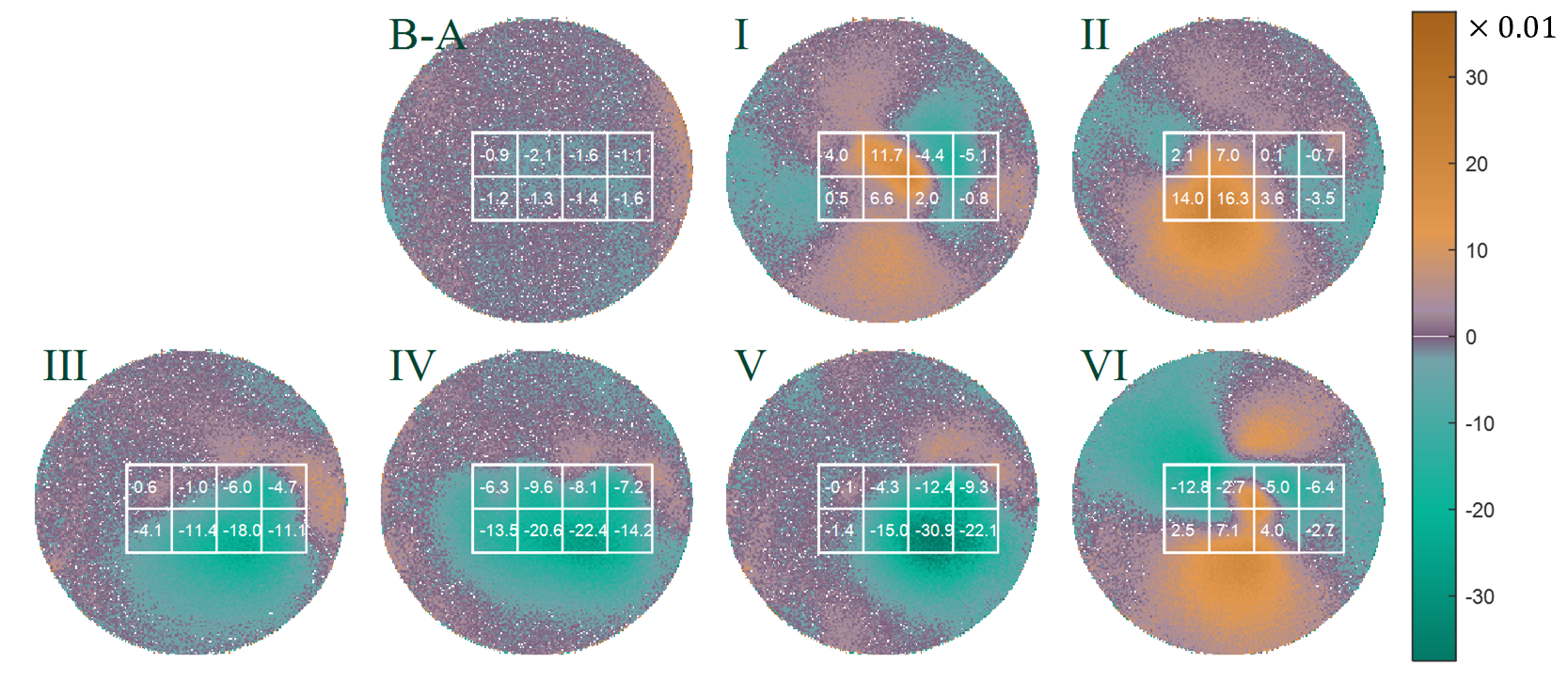
Relative |B1+| map differences. B-A shows the effect induced by placing an unwired cask. Despite the dielectric properties of the slurry only minor changes in the B1+ field are observed for the unwired cask. (I-VI) show the magnitude map differences from figure 3 compared to an unwired case B. Localized and switchable field differences are observable, potentially allowing for homogenization of spatially variable B1+ fields.
DOI: https://doi.org/10.58530/2022/2183