2180
Improving Diffusion MRI in the Posterior Fossa Using a Wireless RF Array at 7T1BioMedical Engineering and Imaging Institute (BMEII), Icahn School of Medicine at Mount Sinai, Manhattan, NY, United States
Synopsis
Ultra-high field (UHF ≥7T) MRI scanners can provide stronger signals than standard field strengths, which boosts signal-to-noise ratio (SNR) for improved diffusion MRI (dMRI). However, at 7T, wavelength effects cause highly inhomogeneous $$$B_1^+$$$ in the human brain, with lower transmit efficiency in the cerebellum and temporal lobes manifesting as signal dropouts in these regions. Recently, we reported a simple approach of using a wireless radiofrequency (RF) array to improve transmit efficiency and signal sensitivity at 7T focusing on the posterior fossa. Here we demonstrate the feasibility and effectiveness of using the RF array for in-vivo dMRI at 7T.
Introduction
Diffusion magnetic resonance imaging (dMRI) at 7 Tesla (7T) provides almost 2 times higher spatial resolution in comparison with the 3T dMRI acquisition1. However, the 7T dMRI acquisition using commercial 1Tx head coils is compromised by flip-angle nonuniformity over the brain2. Typically, a 1Tx head coil is driven in quadrature mode generating circularly-polarized (CP) excitation with highly homogenous $$$B_1^+$$$ at lower field strengths (1.5T and 3T). But at 7T, CP excitation provides highly inhomogeneous $$$B_1^+$$$ in the human brain, with lower transmit efficiency in the inferior temporal lobes and cerebellum manifesting as reduced flip-angle, which results in nonuniform signal and signal dropouts in regions where the $$$B_1^+$$$ is intrinsically low. This inhomogeneity can be mitigated by the use of active RF shimming techniques such as parallel transmit systems (PTx)3 and passive RF shimming methods such as dielectric pads4 and metasurfaces5. However, these methods have some drawbacks such as unstable material parameters and excessively increased flip-angle near dielectric pads, high-cost and complexity of PTx systems, and complex structure of the metasurfaces. In our recent study, we reported a reliable passive RF array6 that was based on an inductive-coupling between the array and the 1Tx head coil, to achieve better transmit efficiency while avoiding the hardware complexity and other disadvantages of these prior methods. Here, we demonstrate the advantages of the array in enhancing 7T in-vivo brain dMRI focusing on the posterior fossa.Method
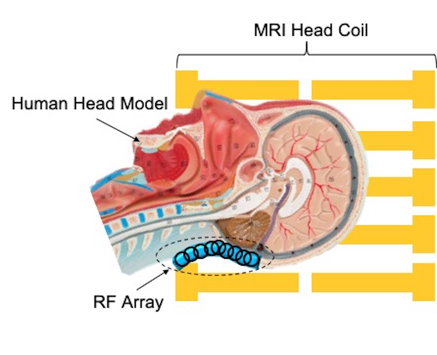
MRI experiments were conducted on a 7T scanner (Magnetom, SiemensHealthcare, Erlangen, Germany) using 1Tx32Rx Nova head coil to collect human brain images on three healthy subjects. The RF array was placed inside the head coil covering the posterior fossa (Fig. 1), which is a common region of reduced transmit efficiency. We experimentally measured $$$B_1^+$$$ maps in the human subject in the presence and absence of the array using saturation-prepared turbo-FLASH (MGH QA Package)7. In-vivo dMRI were obtained with and without the array in a human volunteer with 1.05 mm isotropic resolutions, GRAPPA acceleration factor=3, TE/TR=67.6/7200ms, b-value=1500 s/mm2), 64 diffusion directions and 4 b0 acquisitions, each acquired twice with anterior-posterior (AP) and PA phase encode directions to allow gradient nonlinearity correction in post-processing. Field-of-view was 210x210 mm2, resolution was 200x200x132 mm3, and multiband acceleration factor was 2 with a total scan time of 18.5 minutes. In-vivo dMRI data were first evaluated by calculating the SNR on a voxelwise basis in the cerebellum from b0 images acquired with and without the array in place. The DWI series from both AP and PA directions were then compiled into a single volume, and the combined diffusion image was denoised and corrected. The post-processed diffusion image was used to generate tractography of the Corticospinal tract (CST), Superior Cerebellar Peduncle (SCP), and Inferior Cerebellar Peduncle (ICP) with TractSeg.Results
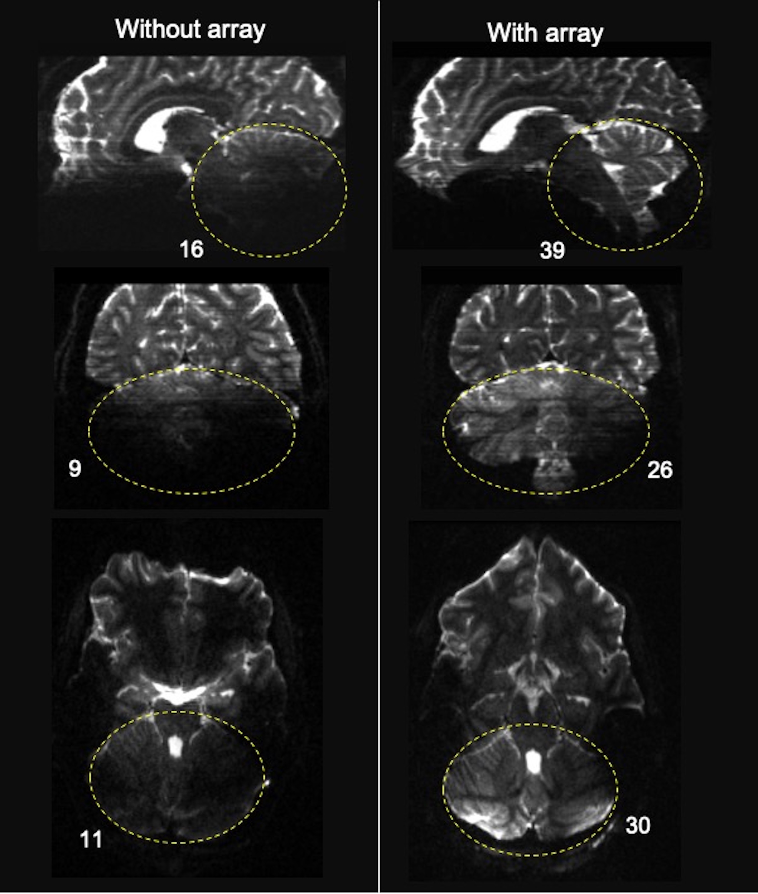
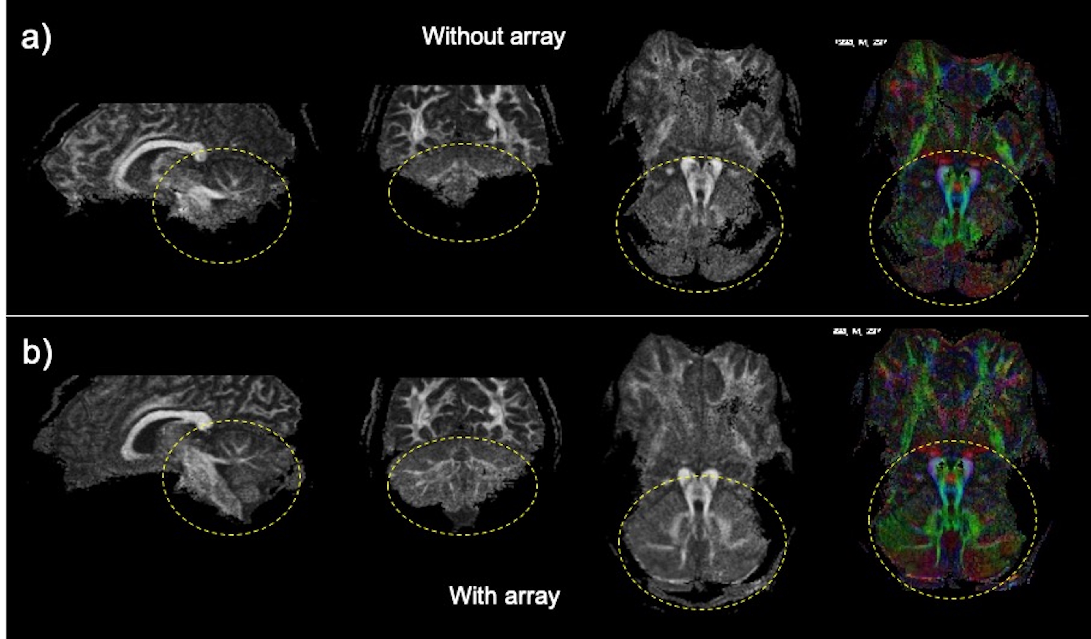
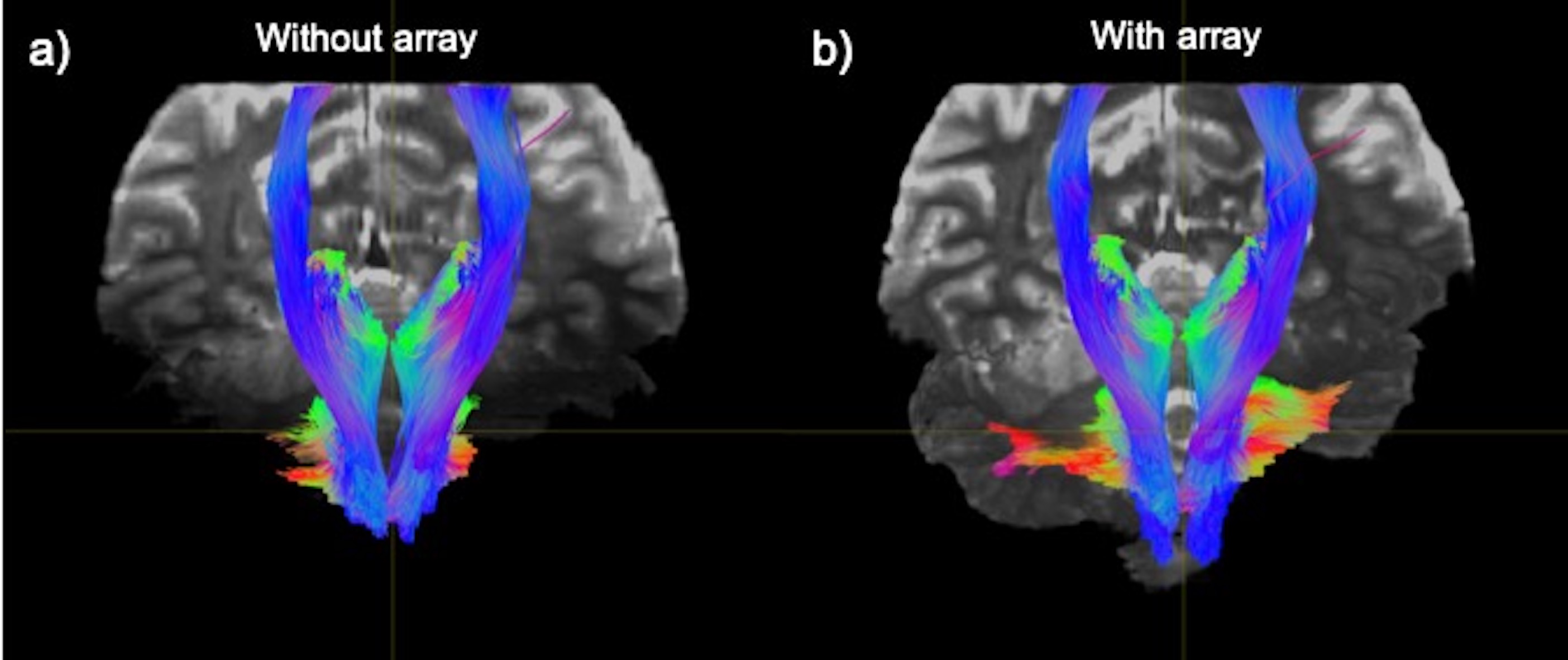
The spatial distribution of the $$$B_1^+$$$ maps in the experiments showed improved performance in the cerebellar region-of-interest (ROI) when the array is present (Fig. 2). The average across the ROI (outlined in dashed black in Fig. 2) showed a mean 2.3-fold improvement in transmit efficiency the presence of the array. The results of our study comparing dMRI with and without the array indicate that the array improves SNR and contrast uniformity in the posterior fossa (Fig. 3). The use of the array effectively improved MR signal in this region and recovered tissue contrast. Quantitative analysis shows an average of 2.6-fold SNR enhancement in the cerebellum (encircled by yellow) in the presence of the array. Figure 4 compared the fractional anisotropy (FA) maps obtained using a 1Tx head coil without (left column) and with (right column) the array. Note that use of the 1Tx head coil without the array yielded lower signal intensity and signal dropouts in the cerebellum; this translated into noisy depictions of principle fiber orientations in these regions. In contrast, the use of the array can significantly improve local signal sensitivity, and by implication SNR and spatial uniformity of SNR. This in turn leads to clear depiction of fibers and better estimation of multiple fiber orientations. Figure 5 displays the tractography generated without (a) and with (b) the array. Improvement in SNR results in enhanced visualization of tracts in the cerebellum and brainstem. Improvement in SNR can be seen as increased conspicuity in cerebellar (red and green fibers moving across) and corticospinal (blue fibers moving up and down) tracts, and in increased coverage of the cerebellum in the background b0 image in the right column.Discussion and Conclusion
We have evaluated the advantages of using the RF array in conjunction with 1Tx head coil configurations for improving cerebellar dMRI at 7T. Our results show that using the array can significantly improve transmit efficiency and signal sensitivity in dMRI of the posterior fossa compared with a standard 1Tx configuration. Most notably, our data suggest that the use of the array can effectively recover signal dropouts in both cerebellum and inferior temporal lobes, leading to a better quantification of principal fiber orientations in those challenging regions. In conclusion, we believe that the array will have great utility for rapid acquisition of high-quality, high resolution whole-brain dMRI, desirable for many neurological and clinical applications.Acknowledgements
This work was supported by an NIH grant (NINDS R21NS122389). All studies involving human subjects were performed in accordance with the MRI safety review board and institutional review board of the Icahn School of Medicine at Mount Sinai.References
[1] Vu AT, Auerbach E, Lenglet C, et al. High-resolution whole brain diffusion imaging at 7T for the Human Connectome Project. NeuroImage. 2015;122:318-331.
[2] Vaughan JT, Garwood M, Collins CM, et al. 7T vs. 4T: RF power, homogeneity, and signal-to-noise comparison in head images. Magn Reson Med. 2001;46:24-30.
[3] Wu X, Auerbach EJ, Vu AT, Moeller S, Lenglet C, Schmitter S, Van de Moortele PF, Yacoub E, Ugurbil K. High-resolution whole-brain diffusion MRI at 7T using radiofrequency parallel transmission. Magn Reson Med. 2018 Nov;80(5):1857-1870.
[4] L. M. Vaidya MV, Deniz CM, et al, "Improved detection of fMRI activation in the cerebellum at 7T with dielectric pads extending the imaging region of a commercial head coil," J Magn Reson Imaging, vol. 48, no. 2, pp. 431‐440, 2018, doi: 10.1002/jmri.25936.
[5] R. Schmidt, A. Slobozhanyuk, P. Belov, and A. Webb, "Flexible and compact hybrid metasurfaces for enhanced ultra high field in vivo magnetic resonance imaging," Scientific Reports, vol. 7, no. 1, p. 1678, 2017/05/10 2017, doi: 10.1038/s41598-017-01932-9.
[6] A. Alipour et al., "Enhanced Ultra-High Field Brain MRI Using a Wireless Radiofrequency Sheet," International Society for Magnetic Resonance in Medicine, 2021.
[7] Klose, U. (1992), Mapping of the radio frequency magnetic field with a MR snapshot FLASH technique. Med. Phys., 19: 1099-1104.
Figures