2179
Effect of Dielectric Resonator (DR) Modes on RF-Magnetic Field1Departments of Neurosurgery and Radiology, College of Medicine, Pennsylvania State University, Hershey, PA, United States, 2Department of Engineering Science and Mechanics, Pennsylvania State University, State college, PA, United States, 3Materials Research Institute, Pennsylvania State University, State college, PA, United States, 4Center for Magnetic Resonance Research, University of Minnesota, Minneapolis, MN, United States, 5Department of Biomedical Engineering, South China University of Technology, Guangzhou, China, 6Department of Electrical Engineering, The Pennsylvania State University, State college, PA, United States
Synopsis
Dielectric resonators with Ultra-High Dielectric Constant (uHDC) materials possess intrinsic resonance modes that have been used for RF transmission and reception. The resonance modes and conditions of the uHDC discs were studied through computer simulations. We compared the B1+ field and RX-sensitivity when employing cylindrical uHDC discs at both resonant and non-resonant conditions. We showed in this work, to achieve the best focusing effect into phantom, the design with uHDC material should operate around the first TE01δ mode and lower than the second mode TE01δ with the highest permittivity.
Introduction
Ceramic discs derived from available uHDC composite have been investigated as an approach to increase RF magnetic field at resonance. Recently, uHDC discs were applied to enhance RF coils transmit efficiency and receive sensitivity at non-resonance conditions. In this case, the intrinsic resonance modes of the uHDC material are avoided because of the potential interferences to the coil’s tuning/matching conditions. This research investigated the question as to whether the uHDC materials can be used at the resonance condition along the conventional RF coils in comparison to the non-resonance cases of the same materials.Method:
To compare the simulation results of previous experimental and analytical work, we consider a well-studied and simple cylindrical dielectric resonator (DR) with known analytical solutions coupled with a circular surface coil (Fig. 1). The design was simulated by using the electromagnetic solver CST Microwave Studio (CST MWS)1. There are three types of resonant modes of an infinite number of each modes that can be excited in this dielectric resonators: transverse electric (TE), transverse magnetic (TM) or hybrid electromagnetic (HEM) modes2. Pure and hybrid modes can be excited and characterized with its magnetic (H) and electric (E) maps, strength, quality factor, and resonance frequency of each mode dependent upon disc geometry, complex permittivity and coupling to the coil; here we are interested in the lower order modes for our applications as only these modes can be strongly coupled to the phantom.Results:
For explored geometry, the fundamental mode is the first transverse electric mode, TE01δ, which produces a strong B1 excitation field, and lower E-field in the phantom. Fig. 2a shows an S11 plot from the coil port, demonstrating the first three lowest resonance modes without and with loading of a phantom. Fig. 2b shows the resonance modes are shifting to lower frequencies when the permittivity increases. Fig. 3 shows the corresponding E and H field distributions of the three modes. The first fundamental mode identified as TE01δ, has the strongest H-field along the axis of dielectric disc and the surface coil, while the other two modes, HEM (f=152 MHz) and TE02δ (f=202MHz), introduce weaker magnetic field coupling to the phantom. As shown in Fig. 2b, at εr=2486 the fundamental resonance of the DR occurs at the operating frequency of the 3T magnet, i.e. 123MHz while at εr=2300 and εr=3000 the fundamental first resonance happens respectively 7MHz higher and 11MHz lower than the operating frequency. By increasing the permittivity to 7000, the second mode also reaches below 123MHz, which cause inhomogeneous field distribution and decreases the RX-sensitivity when it is matched by circuit to 123MHz. Subsequently, the surface coupling coils to the DRs were all tuned/matched to 123MHz using the impedance circuit with < -10dB3. The RX-sensitivity of the coil at eight different permittivity values of the DR listed in Table. I, was calculated and compared with the baseline case where no uHDC material were employed. As shown in Fig. 4 and Fig. 5, the Rx-sensitivity value is enhanced as compared to the baseline by increasing the permittivity up to 4000, and it starts decreasing when operating frequency approaches to the second mode (HEM) for higher permittivity cases more than 5000. So, it should work anywhere before reaching the second mode with highest permittivity value.Discussions and Conclusion:
The RX-sensitivity plots in Fig. 3 indicate that tuning DR by parametric evaluation of permittivity to the operating frequency (123 MHz), although enhancing the SNR dramatically on the surface of the phantom, does not produce the highest average enhancement in whole phantom compared to the baseline. The optimal permittivity of DR for RF field enhancement could be chosen in the way that the operating frequency is between the fundamental (TE01δ) and higher order resonance frequency (i.e. HEM11δ, TE02δ) of DR. The Rx-sensitivity is enhanced significantly (%65) through 3cm inside the phantom compare to the baseline, with Ɛr =4000. Computer modelling of dielectric resonator of a cylindrical disc showed that a coupling surface coil can be easily tuned and matched to the resonance frequency of DR. Our current and future work includes the extension of DR modelling to clinical applications incorporating new coil designs, as well as the study of higher resonant modes (like HEM modes).Acknowledgements
This work is supported by NIH grant U01 EB026978 and U01 EB025144.
References
1. CST Microwave Studio, Ver.2020.
2. Kajfez, Darko, and Pierre Guillon. Dielectric Resonators. Dedham (MA.: Artech House, 1986.
3. Roemer, P B et al. “The NMR phased array.” Magnetic resonance in medicine vol. 16,2 (1990): 192-225. doi:10.1002/mrm.1910160203
Figures
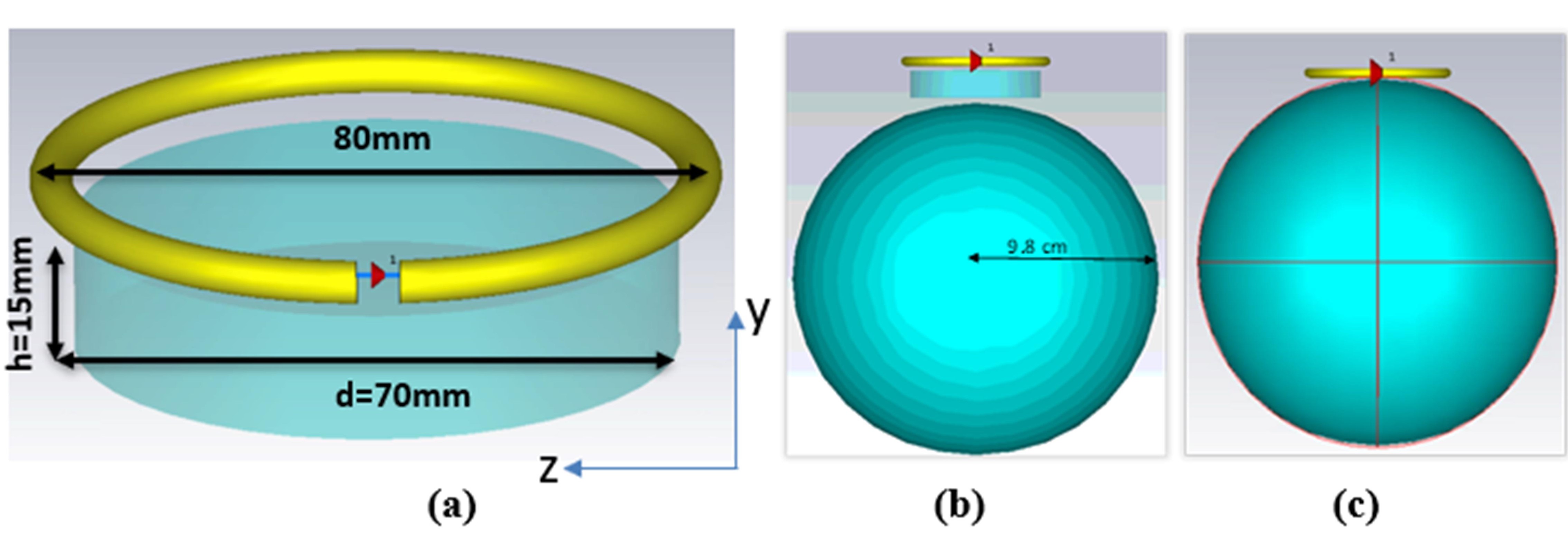
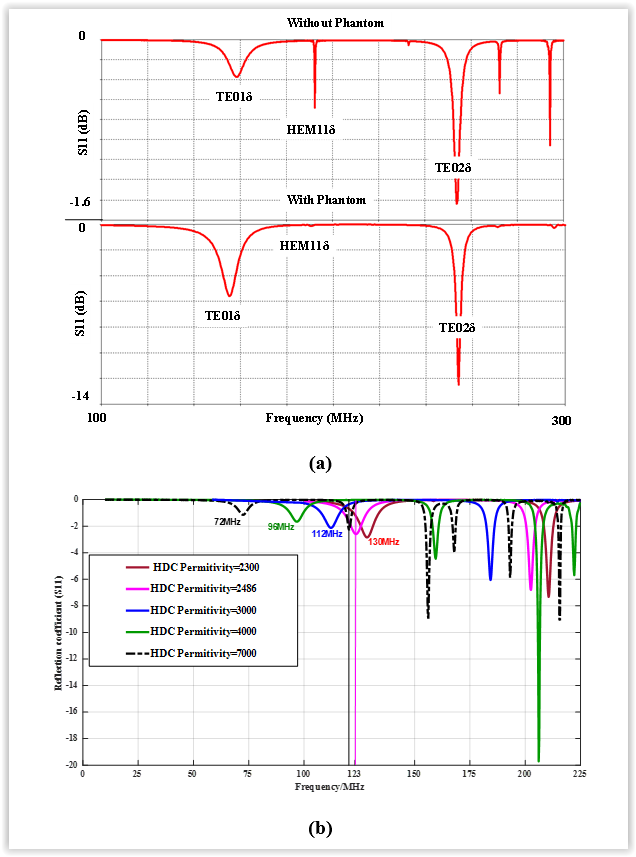
Figure 2: (a) Different resonance modes for both cases (with/out phantom)., (b) S-parameter at different partitivities of uHDC loaded with phantom.
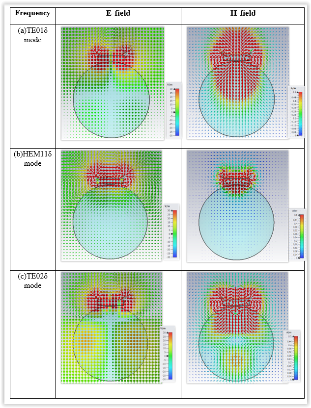
Figure 3: Simulated E-field (123MHz) and H-field (123MHz) of three different modes at permittivity of 2486 from cross-sectional view. (a) TE01δ (f=123MHz), (b)HEM11δ(f=152MHz), (c) TE02δ (f=202MHz).
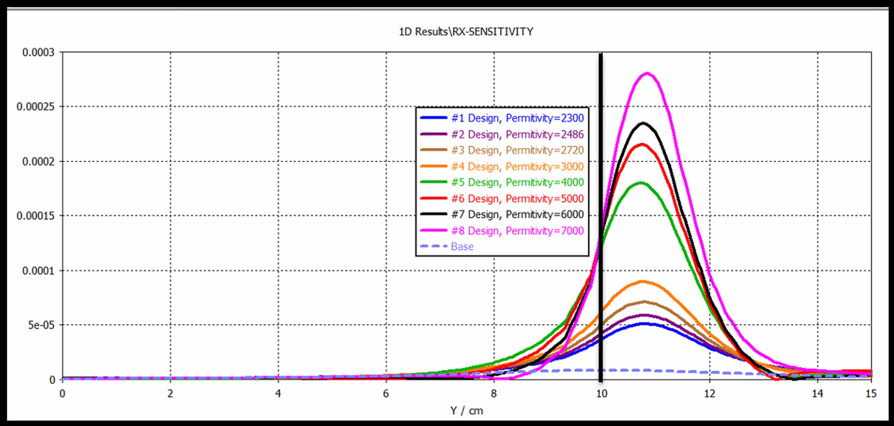
Figure 4) RX-sensitivity of Baseline and with uHDC blocks for different permittivities. The RX-sensitivity is significantly increase for blocks versus baseline. This enhancement region is almost 3cm into the phantom. The center of the phantom is Y=0cm and uHDC is located at Y=10cm.
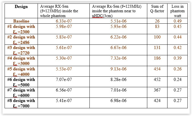
Table I) RX-sensitivity, Q-factor, and loss of baseline and with uHDC blocks at different permittivities. The RX-sensitivity is enhanced significantly (%65) compared to the baseline, with Ɛr =4000.
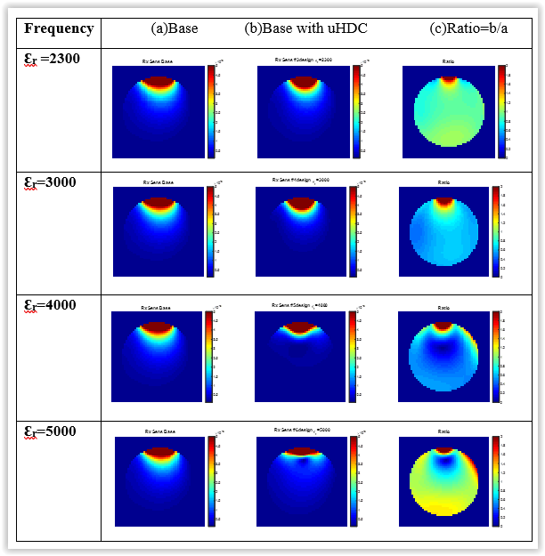
Figure 5) RX-Sensitivity 3D maps at different uHDC permittivities.