2178
Parametric Study of High Dielectric Constant Helmet Characterization1Center for NMR Research, Departments of Neurosurgery and Radiology, Pennsylvania State University, Hershey, PA, United States, 2Center for Magnetic Resonance Research, University of Minnesota, Minneapolis, MN, United States, 3Department of Engineering Science and Mechanics, Pennsylvania State University, State college, PA, United States, 4Materials Research Institute, Pennsylvania State University, State college, PA, United States, 5Department of Biomedical Engineering, South China University of Technology, Guangzhou, China
Synopsis
Helmets conformal to the human head with high or ultra-high dielectric constant (HDC/uHDC) materials have been shown to enhance the SNR of entire human head along with a receive array. However, the dielectric resonance modes (DRMs) of the helmet have not been studies systematically. This investigation aimed to; 1) describe the characteristics of the DRMs and their RF field distributions; 2) establish the relationships between DRMs and the basic geometric parameters of the helmet using numerical modeling. Understand the DRMs of large uHDC structures are fundamentally important for future applications of uHDC materials for RF field reach.
Introduction
Helmets conformal to the human head with high or ultra-high dielectric constant (HDC/uHDC) materials have been attempted to enhance the SNR of head receive array at 3T, 7T and 10.5T 1-3. Experimental data acquired with HDC/uHDC helmet have demonstrated significant SNR improvements and transmit power reduction. To optimize the design and incorporate the helmet into standard head receive array, we have to understand and optimize several parameters, such as: geometries (thickness, shape, etc.) and permittivity of the helmet, coil array geometries, and configurations. More importantly, in a large continuous dielectric structure such as a helmet, standing waves and dielectric resonance mode (DRM) of the RF field are likely to form in the helmet because the wavelength of the RF field is shorter than the helmet dimensions, which further complicates the optimization problem. This investigation aimed to; 1) describe the characteristics of the DRMs and their RF field distribution; 2) establish the relationships between DRMs and the basic geometric parameters of the helmet using numerical modeling.Method:
A continuous HDC helmet fit to a human head were simulated by CST Microwave Studio 20204 and fabricated both shown in Figure 1. The HDC material for the purpose of simulation and experiment was the BST ceramic powder mixed into water slurry (εr = 152.8 and Tangent delta = 0.05). We want to investigate the S-parameter results from different types of helmet excitations and effect of helmet’s different factors on the resonance; consequently, we used two different types of excitations: 1) waveguide excitation and 2) coil excitation. Waveguide port represents the surface through which a RF input as pseudo plane wave enters or exits as none-reflective radiation boundary. CST generates a solution by exciting each wave port individually and uses 2D eigenmode solver to calculate the waveguide port modes3. Waveguide excitation removed the influences of coupling/tuning/match issues associated with RF coil excitation. S-parameter plot was measured on benchtop with a pair of pickup coil (Figure 3).Results:
Figure 2(a), (b) illustrates the simulated S-parameter by using the waveguide port and coil excitations, respectively. As it shows, by 90-degree difference in excitation position (1st back to front, 2nd right to left), the S-parameter plots show similar dielectric resonance modes in the helmet. The frequencies of the DRMs shifted because the helmet is elliptical in shape and electric path of the DRM are slightly different. Accordingly, benchtop measurement setup and experimental S-parameter plots are also shown in Figure 3. The dielectric resonance modes excited from different positions of the coil around the helmet and measured at the center inside the helmet.The RF field distributions were evaluated for all modes and we focused on optimization the first DRM with frequency f=294MHz which give us more homogeneous magnetic field distribution as seen in Figure 4. Both simulated and measurement results have similar trend almost around 300MHz (1H resonant frequency at 7T). Figure 4 shows the Ez-Field in the and very homogenous H-field inside the HDC helmet at f=294MHz. Also, the parametric study of the helmets’ thickness, height and permittivity effect on the resonance frequency are shown in Figure 5. By increasing the HDC permittivity the resonance modes shift to lower frequencies. On the other hand, by decreasing the length and thickness of the helmet the resonance modes shift to higher frequencies.
Discussions and Conclusion:
We examined the lower order modes of dielectric resonance modes for MR imaging applications as these modes are more strongly coupled to the phantoms and have more homogeneous field distributions and improved SNR values. Optimization of the HDC structure and helmet performance at a desired resonant frequency three independent parameters such as permittivity, thickness, and height of HDC helmet were shown to be effective.Acknowledgements
This work was supported in part by NIH grants of U01 EB026978, R01 CA240953 and P41 EB027061.
References
- Sica CT, Rupprecht S, Hou RJ, et al., Toward whole-cortex enhancement with an ultrahigh dielectric constant helmet at 3T. Magn Reson Med. 83:1123-1134 (2020)
- Gandji, Navid P et al., Displacement current distribution on a high dielectric constant helmet and its effect on RF field at 10.5 T (447 MHz). Magn Reson Med. 86: 3292-3303 (2021).
- Chen W, Lee BY, Zhu XH, et al., Tunable Ultrahigh Dielectric Constant (tuHDC) Ceramic Technique to Largely Improve RF Coil Efficiency and MR Imaging Performance. IEEE Trans Med Imaging 39:3187-3197 (2020).
- CST Microwave Studio, Ver.2020.
Figures
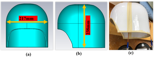
Figure 1: (a) Front view of the HDC helmet (b) Side view of the HDC helmet. (c) Fabricated HDC helmet with the permittivity of 152.8
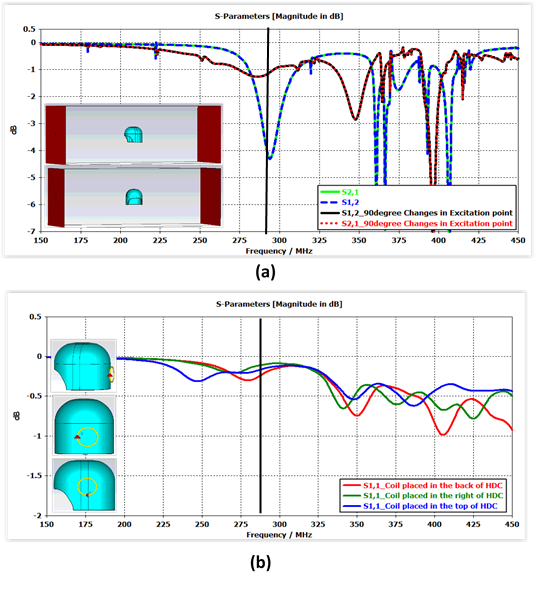
Figure 2: (a) S-parameter simulation results for the waveguide excitation from right to left and back to front, and (b) S-parameter results by coil excitation from different positions. For both cases we are interested in the first HDC intrinsic resonance mode near to 300MHz (1H resonant frequency at 7T).
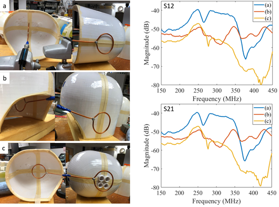
Figure 3: The measurement set up and S-parameter results from different points of excitation (port 1, right row) and reception (port 2, left row): (a) center (port 2) to side (port 1), (b) center (port 2) to posterior (port 1), (c) center (port 2) to top (port 1). Note in (c), the reception port 2 is oriented to measure the longitudinal H field. For all cases we are interested in the first HDC helmet intrinsic resonance mode near to 300MHz (1H resonant frequency at 7T).
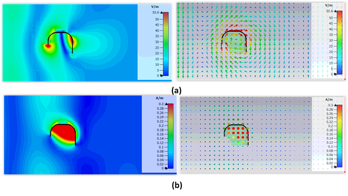
Figure 4: Simulated average magnitude (left column) and vector (right column) plots of (a) Ez component and (b) H-field distributions of the fundamental mode at 294MHz. Only Ez component is shown because it produces the transverse H-field of our interest. In this mode, the H-field is uniform and dominantly in the transverse plane (x-y) inside the helmet similar to that of a birdcage RF coil.
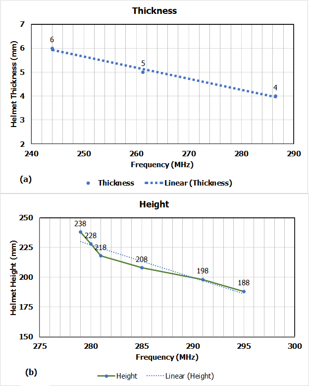
Figure 5: Parametric study of helmet Height and Thickness effects on the dielectric resonance mode frequency.