2148
Platform for Real-Time Multiplane Targeting and Monitoring of Minimally-Invasive Image-Guided Prostate Cryoablation Procedures1Medical Physics, University of Wisconsin - Madison, Madison, WI, United States, 2Radiology, University of California - San Francisco, San Francisco, CA, United States, 3Radiology, Mayo Clinic, Rochester, MN, United States, 4Radiology, University of Wisconsin - Madison, Madison, WI, United States, 5Biomedical Engineering, University of Wisconsin - Madison, Madison, WI, United States, 6Interventional Radiology, University of Wisconsin - Madison, Madison, WI, United States
Synopsis
Minimally invasive cryoablation is an effective and safe treatment option for localized low- and intermediate-risk prostate cancers. Precisely placed cryoprobes in cancerous regions of the prostate kill malignant cells by freezing local tissues while being less invasive than prostatectomy, and having a shorter treatment cycle than most radiotherapies. For accurate probe placement, MR-image guidance is often employed, coupled with external probe-guiding apparati. We developed a platform that enables a cohesive workflow to register the probe-guiding apparati, facilitate target selection, select and verify probe trajectory, and monitor the prostate in real-time using multiple planes during probe insertion and cryoablation freeze cycles.
Introduction
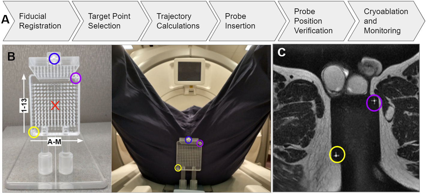
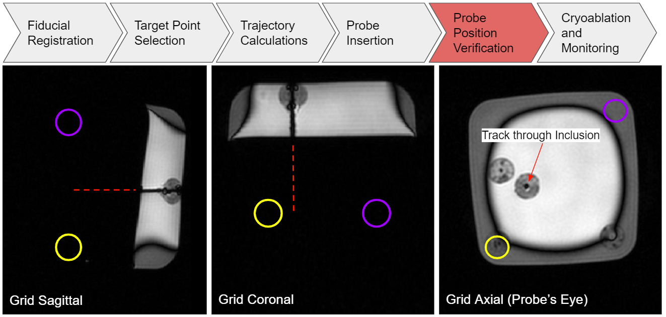
Interest continues to grow for prostate cancer treatments that remain effective while offering patients reduced treatment/recovery times or sparing more non-cancerous tissue. Cryoablation of prostate cancer is a minimally invasive, single session treatment best-suited for low- and intermediate-risk cancers that are localized and visible on diagnostic MRI1,2,3,4. Guiding the insertion of multiple cryoprobes5, verifying cryoprobe placement, and monitoring of treatment is all possible with simple trajectory guides (Fig. 1B) and common MR sequences (Fig. 1C).Integrating the workflow of necessary steps (Fig. 1A) is difficult on commercially available diagnostic scanners. Abstracting away the complexity of driving the MR scanner is necessary for widespread adoption by interventional radiologists.
Previous MR-guided implementations alternated between commercial MR image acquisition and off-line computation to determine entry coordinates on trajectory guides and prescribe the imaging planes needed to verify cryoprobe placement and monitor cryoablation (Fig. 2). We instead use a real-time, multi-vendor MR interface (RTHawk, Los Altos CA)6 to create a platform that diminishes workflow complexity. A cohesive framework allows geometric information from previous steps to be inherited by subsequent steps (Fig. 1A) for identifying trajectory guide fiducials, selecting cancerous target points within the prostate, calculating probe trajectories to targets, and real-time imaging along and perpendicular to the probes during before, during, and after cryoprobe insertion.
Methods
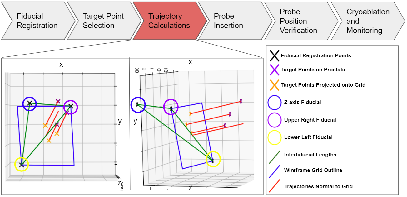
We have integrated and validated four of the procedure’s six steps shown in Figure 1A into the RTHawk interface. The Trajectory Computation step, shown in Figure 3, must be ported from Python to RTHawk’s Javascript before final integration with a custom clinical cryoablation device that will be delivered within two months.Fiducial Registration:
The external cryoprobe guidance grid (Fig. 1B), featuring three fiducials, is often not placed co-linearly with the magnet z-axis to support oblique trajectories. These fiducials present with high contrast in T2-W MRI for identifying grid location and orientation. Our platform allows users to denote the central coordinate of each fiducial in the scanner bore reference frame. Based on fitting a model of known fiducial geometry to the denoted points, we generate a second coordinate system orthonormal to the grid and establish a transformation between the device and scanner coordinate systems.
Targeting and Trajectory:
Users then place one target point for each cryoprobe to be inserted into the prostate. The platform projects each target point onto the grid face, thereby determining the grid hole and depth of insertion that defines the best trajectory to reach the target point (Fig. 3). This geometry information is relayed through custom RTHawk applications that support selection of oblique planes collinear and perpendicular to the probes from which to view the prospective trajectory prior to insertion and monitor cryoablation in real-time. The selection of these planes is intended to mimic the capabilities of common stereotactic image-guidance workstations.
Procedure Monitoring:
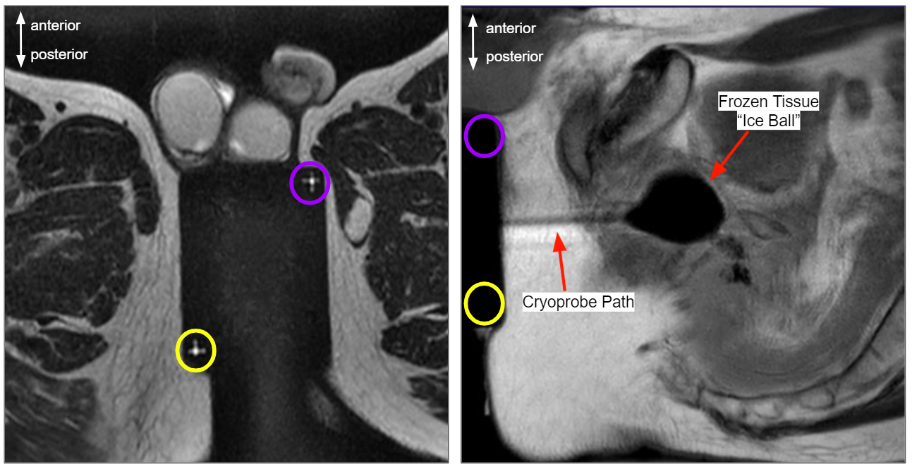
Knowing the intended probe trajectory, our application can rotate the scanner’s acquisition planes about this trajectory or translate the monitored plane off the probe, allowing for any desired view-plane7. In this way, interventionists may orient their guiding images freely to observe and adjust probe placement prior to the procedure, in addition to monitoring the growing and shrinking of the induced ice ball during the freezing and thawing cycles of treatment.
In Vitro Validation:
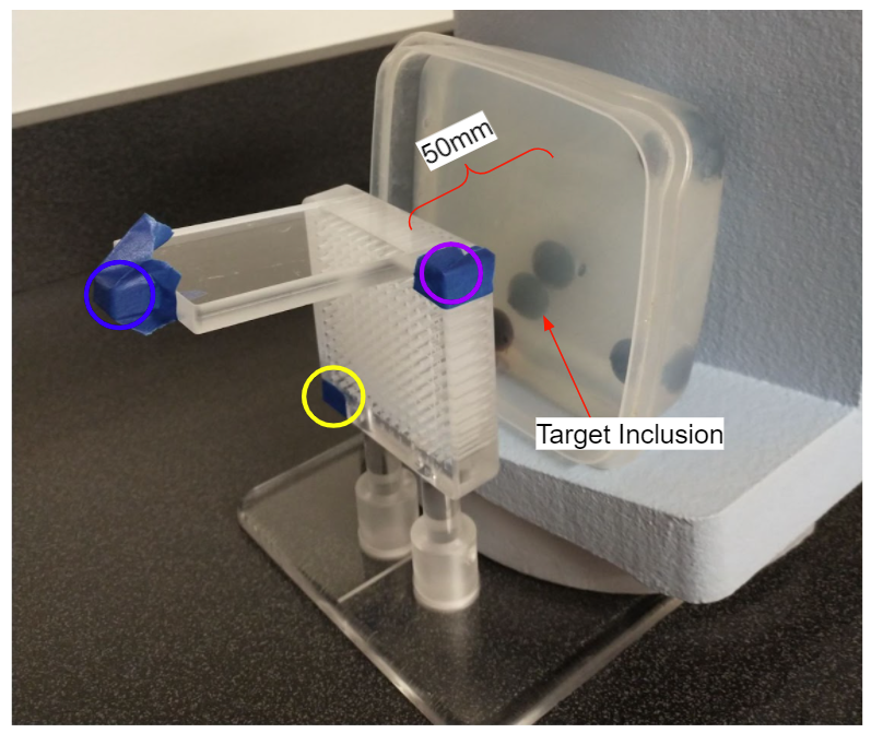
To verify trajectory accuracy, we created a simple gelatin phantom with several blueberries added to serve as cancerous inclusions in a greater prostate volume (Fig. 4). Grid fiducials were located and target points were selected at the centers of the inclusions. Based on the tool’s calculations of these relative points, our software determined grid entry holes for each target and MR-safe biopsy needles were inserted into the named holes. High resolution CUBE T2 MR scans were taken with needles inserted for analysis (Fig. 5).
Results
The proposed platform directed cryoprobe analogues to targeted inclusions within the phantom, as tested over a set of varied oblique grid orientations and ten target locations. Average radial error was 1.05±0.38mm. Probe insertion was viewable via real-time MR.Discussion
The developed methods enabled us to consistently guide cryoprobes within 1.05±0.38mm of the intended target points on our prostate phantom while allowing free reorientation of the view-plane, rotationally or translationally. Furthermore, real-time imaging was available at any stage of the process. Grid design presented a limitation on maximum attainable accuracy due to 5mm interhole grid spacing. However, since iceball growth around the probe is monitored and can be controlled only to within a few mm, probe placement is conservatively planned around sensitive anatomy. Given these limitations, the quantized location of translated trajectories is acceptable.Conclusion
The platform allowed users to accurately guide cryoprobes to targeted locations while eliminating much of the complexity in driving the scanner. The platform enabled free re-orienting of the interventionist’s view-plane for real-time imaging at any stage of the procedure. Future work includes integrating the platform with our new cryoprobe driver before incorporating the platform in human trials later this spring.Acknowledgements
This work was completed with funding from the University of Wisconsin School of Medicine and Public Health and the UW Department of Radiology.
We thank the Mayo Clinic Interventional MRI Program and Mayo Clinic Department of Engineering, through which the perineal grid was developed.
We acknowledge GE Healthcare for research support.
References
[1] Haker SJ, Mulkern RV, Roebuck JR, Barnes AS, Dimaio S, Hata N, Tempany CM. Magnetic resonance-guided prostate interventions. Top Magn Reson Imaging. 2005 Oct;16(5):355-68. doi: 10.1097/00002142-200510000-00003. PMID: 16924169.
[2] Litwin MS, Tan H. The Diagnosis and Treatment of Prostate Cancer: A Review. JAMA. 2017;317(24):2532–2542. doi:10.1001/jama.2017.7248
[3] S. Adamis, I.M. Varkarakis,Defining prostate cancer risk after radical prostatectomy, European Journal of Surgical Oncology,Volume 40, Issue 5, 2014,Pages 496-504
[4] D.A. Woodrum, A. Kawashima, R.J. Karnes, B.J. Davis, I. Frank, D.E. Engen, et al.Magnetic resonance imaging-guided cryoablation of recurrent prostate cancer after radical prostatectomy: initial single institution experienceUrology, 82 (2013), pp. 870-875
[5] Yiu WK, Basco MT, Aruny JE, Cheng SW, Sumpio BE. Cryosurgery: A review. Int J Angiol. 2007;16(1):1-6. doi:10.1055/s-0031-1278235
[6] J. M. Santos, G. A. Wright and J. M. Pauly, "Flexible real-time magnetic resonance imaging framework," The 26th Annual International Conference of the IEEE Engineering in Medicine and Biology Society, 2004, pp. 1048-1051, doi: 10.1109/IEMBS.2004.1403343.
[7] Ozhinsky E, Salgaonkar VA, Diederich CJ, Rieke V. MR thermometry-guided ultrasound hyperthermia of user-defined regions using the ExAblate prostate ablation array. J Ther Ultrasound. 2018 Aug 13;6:7. doi: 10.1186/s40349-018-0115-5. PMID: 30123506; PMCID: PMC6088423.
Figures