2060
MoCoPad: A new soft sensor system for fast head motion detection and tracking in MRI
Saikat Sengupta1,2, Mishek Musa3, and Yue Chen4
1Vanderbilt University Institute of Imaging Science, Nashville, TN, United States, 2Department of Radiology, Vanderbilt University Medical Center, Nashville, TN, United States, 3Department of Mechanical Engineering, University of Arkansas, Fayetteville, AR, United States, 4Department of Biomedical Engineering, Georgia Institute of Technology, Atlanta, GA, United States
1Vanderbilt University Institute of Imaging Science, Nashville, TN, United States, 2Department of Radiology, Vanderbilt University Medical Center, Nashville, TN, United States, 3Department of Mechanical Engineering, University of Arkansas, Fayetteville, AR, United States, 4Department of Biomedical Engineering, Georgia Institute of Technology, Atlanta, GA, United States
Synopsis
In this abstract we present initial feasibility results of a novel pneumatic sensor-based head motion detection and tracking system for MRI. The system comprises of head pad with a built in matrix of air pressure sensors, which replaces the standard head pad in an MRI scan and allows fast sequence agnostic tracking of head motions without the need for navigators, head markers or camera systems. Here, we show initial results for motion detection and head pose estimation in phantom studies using a motion model trained outside the scanner.
INTRODUCTION
Head motions continue to be a major source of artifacts in structural and functional brain MRI.1-4 Compatibility with existing scan protocols and ease of adoption are important considerations when selecting a motion tracking method. In this work we present initial feasibility results of MoCoPad, a novel pneumatic sensor-based head motion detection and tracking system for MRI. The system comprises of head pad with a matrix of air pressure sensors, which replaces the standard head pad in an MRI scan, and allows completely sequence and coil agnostic, fast tracking of head motions without the need for navigators, head markers or camera systems. Here in, we describe the construction, setup, modeling and initial motion detection and head pose estimation results in phantom studies in a 3T scanner.METHODS
Sensor Pad and Data Acquisition. The sensor pad (Figure 1A) contains a head coil sized silicone rubber pad with a 4 x 4 grid of air chamber sensors. The chambers are connected to a RF shielded box with 16 analog pressure sensors (ABPDANV060PGAA5, Honeywell Inc, IN, USA) using 10 feet long 3.175 OD plastic pneumatic tubes. 16 channel data from the pressure sensors are digitized by an Arduino microprocessor at a baud rate of 115200 bit/s (10 bits/channel, 160 bits/reading, 1.38 ms/reading)5. Data are recorded continuously by a computer outside the scanner room via a shielded USB connection.Motion Modeling A calibration model is needed to relate the head motion associated pressure changes in the sensor cells to the degree of head rotation. In this work, we trained a Gaussian Process Regression (GPR)6 based deep learning model using a head phantom on the bench, outside the scanner (Figure 2A). An optical motion tracker (Microntracker, Claronav, Toronto, Canada) was used measure head pose while the phantom was rotated at 100 random angles about the foot-head axis, with simultaneous recordings of pressure data. 80 data points where used to train the model with k = 5 k-fold cross-validation. The remaining 20 points were then used as test data to evaluate the model.
Scanner Experiments : We performed two experiments on a 3T Philips Elition scanner with the 2-channel body transmit/receive coil to test the feasibility of the technique.
Motion Detection and Frame Rejection: In the first experiment, we tested the ability of the system to detect head motion, and guide data rejection. We performed two 40 dynamic, single shot EPI scans (FOV 240 mm2, 2.4 mm3 voxels, 36 slices, R = 2, TR/TE = 2046/30 ms, Tacq = 87 secs), where the phantom was manually moved to an in-plane rotated position for a few dynamics and returned back to the initial (or close to) position. Motion corrupted volumes were identified from time-stamped sensor data retrospectively and removed from the time series. Temporal signal to noise (TSNR) over the volumes were then compared between data with and without motion frame rejection.
Motion Estimation: In this experiment, we tested the feasibility of motion estimation based on sensor pad data. We acquired single slice data with two sequences: a 2D GRE with FOV 256 mm2, 2 x 2 x 4 mm3 voxels, TR/TE = 40/2.1 ms, flip = 12 deg, Tacq = 5 secs and a 2D multishot EPI with FOV 228 x 228 mm2, 1 x 1 x 4 mm3 voxels, EPI fac 19, TR/TE = 2000/30 ms, Tacq = 56 secs. Data were collected in three phantom positions, with the first reference position aligned with the 0 degree bench trained position. Sensor pad data were used to estimate motions retrospectively and compared to motions estimated by image registrations in matlab. To derive motions about the center of the image, we identified the pivot point in moved vs reference difference images and transformed the sensor pad rotation (which are modeled off the bottom of the phantom) to in-plane rotation and translations about the center of the image.
RESULTS
The on-the-bench motion model calibration showed high accuracies of 0.18 and 0.32 degrees of RMSE for the training and testing data (Figure 2B). Figure 3 shows results from the motion detection experiment. The sensor pressure data clearly depicted the change in head pose and head rotations estimated from the timestamped data allowed easy identification and rejection of the motion corrupted volumes. TSNR values computed for the whole phantom where significantly higher with frame rejection (12.86, 10.68) compared to without (8.16 and 7.38) for the two scans. Figure 4 shows results of the motion estimation. Motions estimated from sensor pad were close to the motions estimated from image registrations for both GRE and mshEPI, with maximal absolute translation and rotation errors being 3.74 mm and 1.57 degrees respectively.DISCUSSION
In this work we have presented feasibility results of a novel head motion tracking system that is based on monitoring pressure changes caused by a moving head. The system does not interfere with the MRI sequence, does not impact patient comfort and is fast (1.38 ms/motion update) allowing for the potential prospective corrections by integrating with the scanner’s respiratory triggering system. Future work will focus on minimizing errors in motion estimation, developing fast in-scanner calibrations and developing prospective corrections.Acknowledgements
This work was supported by NIH EB02558. We are very grateful to Dr William A Grissom and Dr Adam Anderson for valuable comments and advice.References
- Maclaren J, Herbst M, Speck O, Zaitsev M. Prospective motion correction in brain imaging: a review. Magn Reson Med. 2013 Mar 1;69(3):621-36. PMID: 22570274
- Slipsager JM, Glimberg SL, Søgaard J et al. Quantifying the Financial Savings of Motion Correction in Brain MRI: A Model-Based Estimate of the Costs Arising From Patient Head Motion and Potential Savings From Implementation of Motion Correction. J Magn Reson Imaging. 2020 Sep;52(3):731-738. doi: 10.1002/jmri.27112. Epub 2020 Mar 7. PMID: 32144848.
- Havsteen I, Ohlhues A, Madsen KH, et al. Are Movement Artifacts in Magnetic Resonance Imaging a Real Problem?-A Narrative Review. Front Neurol. 2017 May 30;8:232. doi: 10.3389/fneur.2017.00232. PMID: 28611728; PMCID: PMC5447676.
- Godenschweger F, Kägebein U, Stucht D, et al Motion correction in MRI of the brain. Phys Med Biol. 2016 Mar 7;61(5):R32-56. PMID: 26864183
- Arduino LLC, Boston, Massachusetts, 02116, USA
- Rasmussen CE and Williams,CKI Gaussian Processes for Machine Learning. Cambridge, MA: MIT Press, 2006.
- Shmueli K, Thomas DL, Ordidge RJ. Design, construction and evaluation of an anthropomorphic head phantom with realistic susceptibility artifacts. J Magn Reson Imaging. 2007 Jul;26(1):202-7. doi: 10.1002/jmri.20993. PMID: 17659546.
Figures
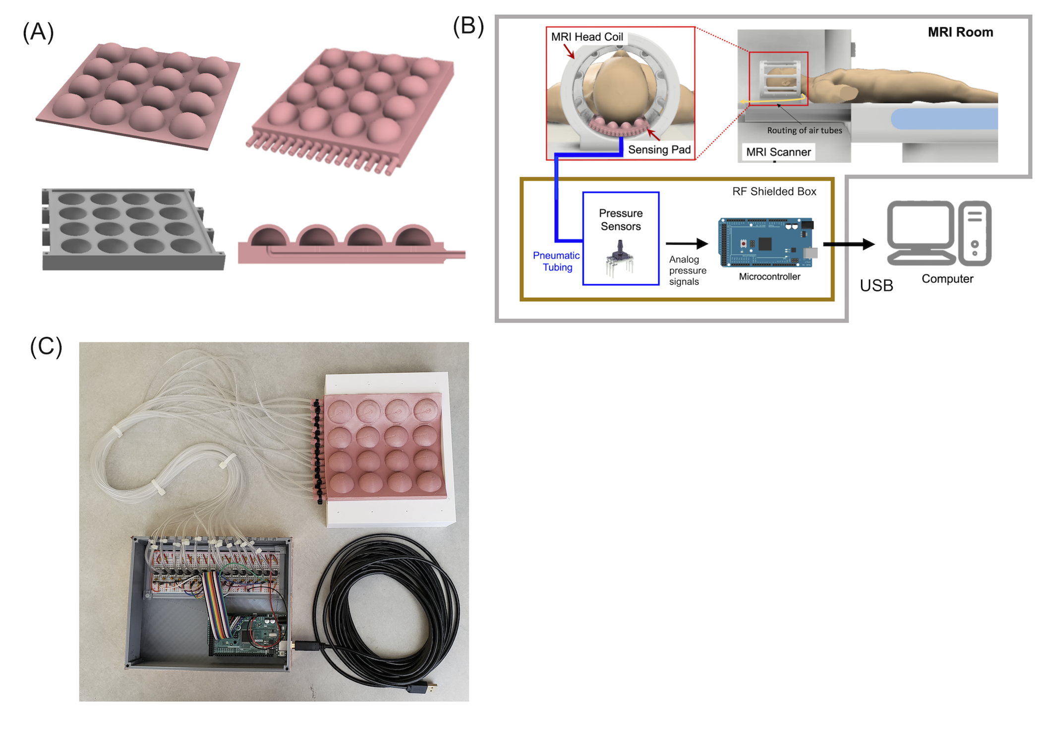
Figure 1. The MoCoPad system. (A) The 4 x 4 grid soft sensor pad with internal air spaces and air pressure channels (B) Integration of the pad in an MRI scan. The pad replaces a standard head pad. Pressure data are recorded continuously using pressure sensors and a microprocessor. (B) Picture of the actual system used in this work. The tubes shown here were replaced with 10 feet long tubes to sufficiently separate the sensors from the scanner bore.
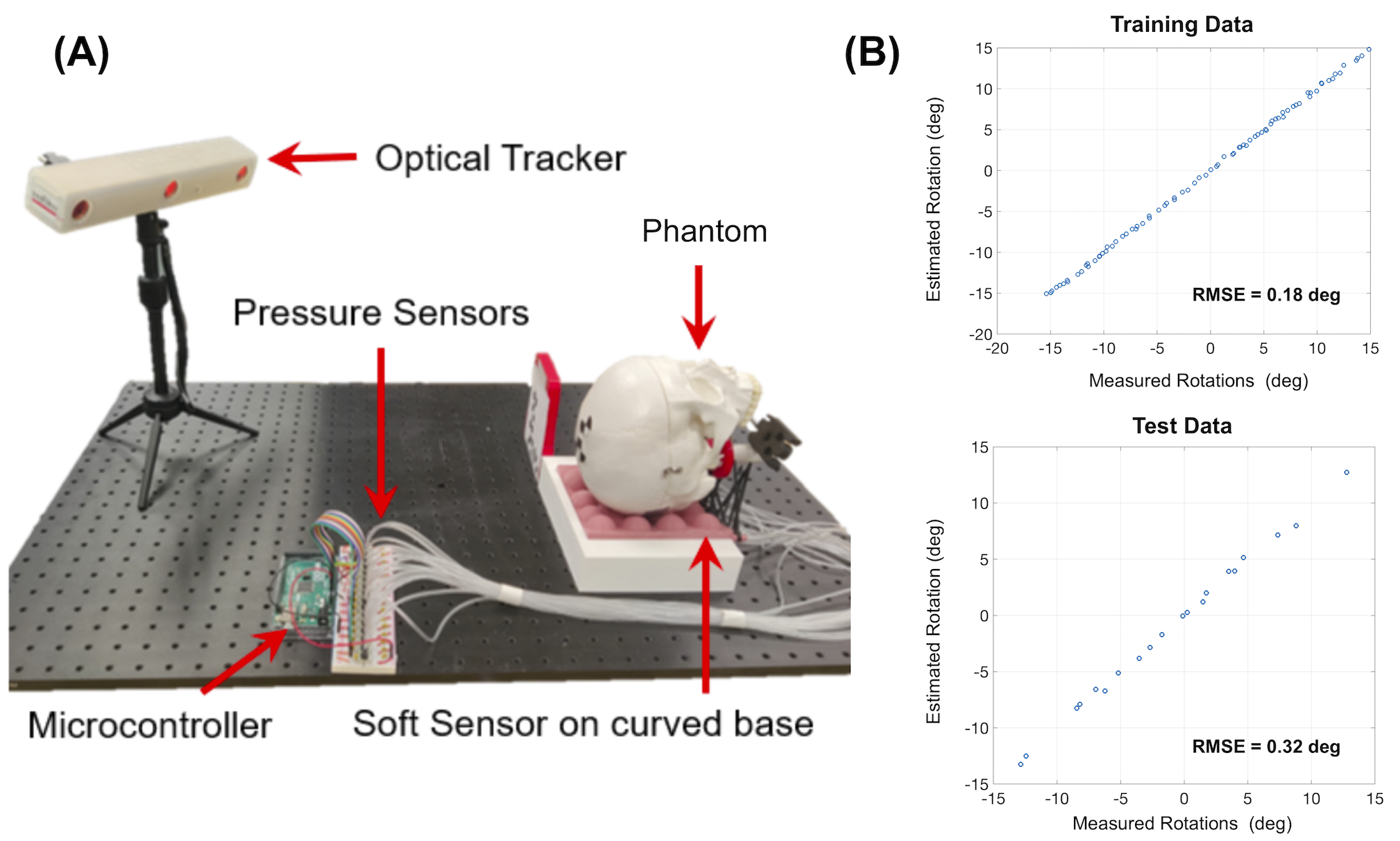
Figure 2 . On the bench system calibration. (A) An optical tracking setup was used to calibrate the motion model outside the scanner. The phantom shown here was replaced with an anthropomorphic phantom with realistic human tissue properties.7 (B) Plots of training and testing data with RMS errors from optical tracker positions. High accuracy was achieved in bench testing (RMSE = 0.32 deg).
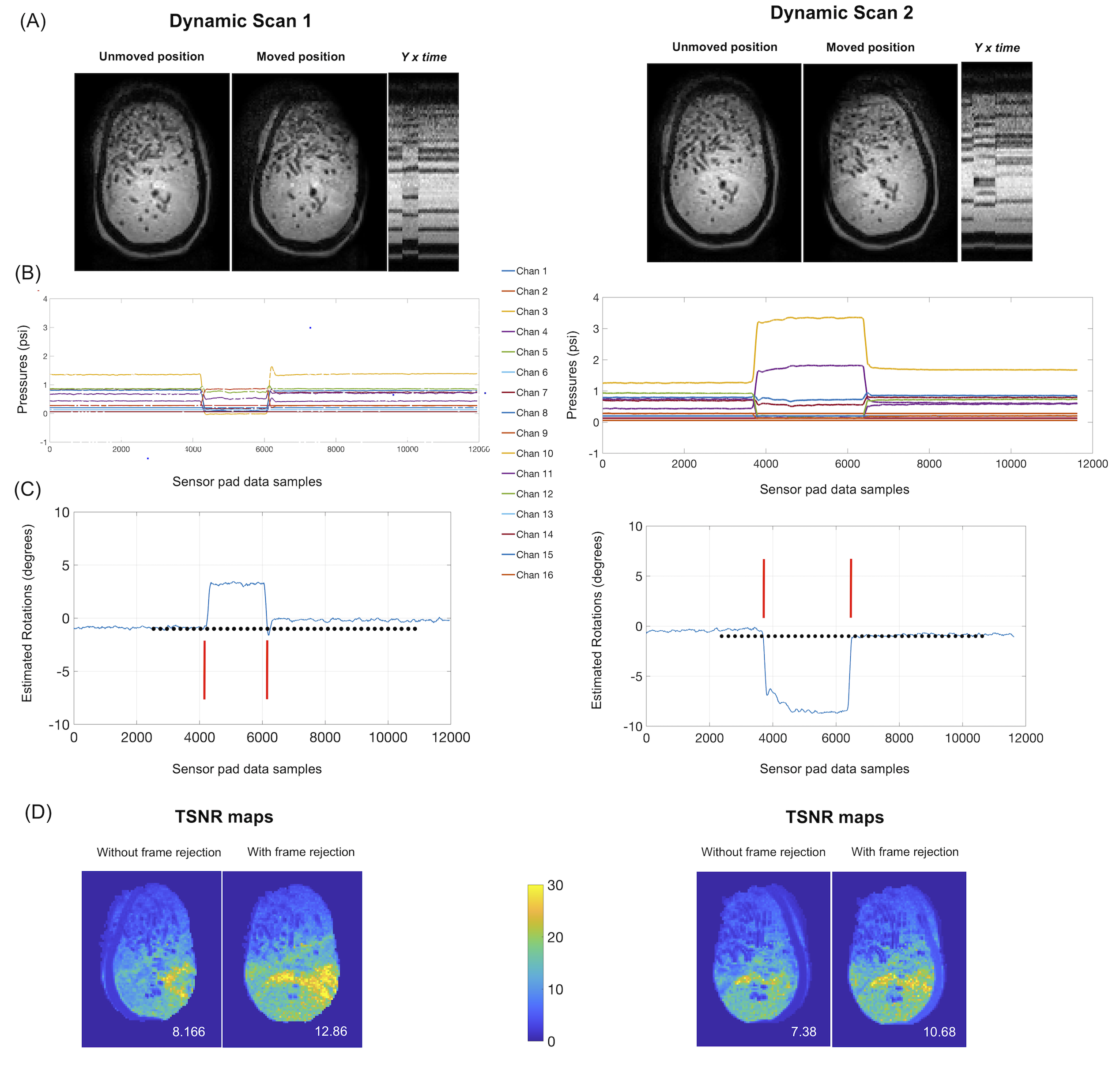
Figure 3 Results of motion detection experiment: (A) Central slices from the EPI volumes in the initial and moved positions, and Y x Time projection images showing motion incident, in different directions. (B) 16 channel (moving average filtered, 100 window) pressure data from the sensor pad (C) Retrospectively estimated head rotations using sensor data and motion model, along with 40 dynamic time stamps (black dots) and frame rejection window (red lines). (D) TSNR maps without and with frame rejection.
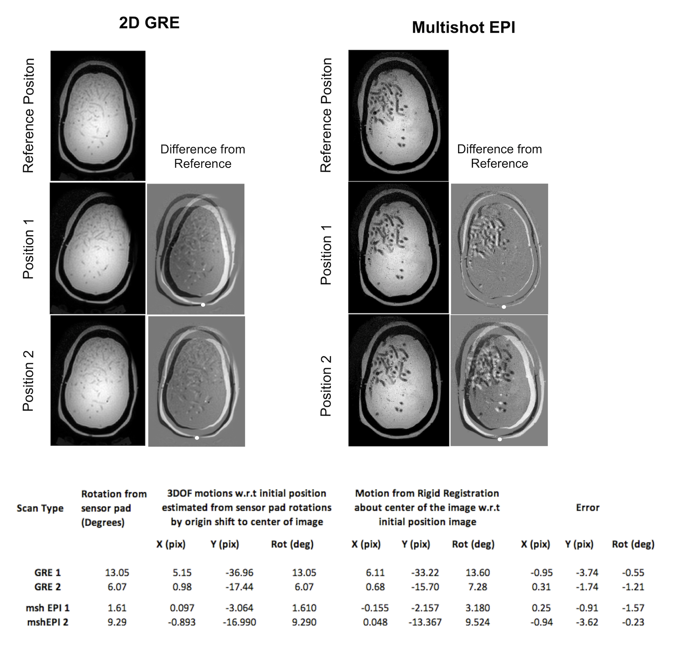
Figure 4 Results of motion estimation experiments. 2D GRE and Multishot EPI images in three different head positions. Difference images with manually selected pivot point (white dots) selected where the difference amplitude is minimum. Bottom : Table of estimated rotations from sensor pad and image registrations along with errors in inplane motion estimates.
DOI: https://doi.org/10.58530/2022/2060