2053
On the concept of long-range short-wave motion tracking
Christoph Michael Schildknecht1 and Klaas Paul Prüssmann1
1Institute for Biomedical Engineering, ETH Zurich and University of Zurich, Zürich, Switzerland
1Institute for Biomedical Engineering, ETH Zurich and University of Zurich, Zürich, Switzerland
Synopsis
Current motion tracking modalities operate either in frequency bands that are also occupied by the MRI scanner or interact heavily with the environment. As an alternative, the frequency band of 1-5 MHz can be utilized for motion tracking and has been demonstrated to deliver high performance. Due to the limited sensitivity at a great distance of current broadband systems, we show in this work how short-wave motion tracking can be done at long ranges, enabling independent and robust motion tracking with fewer geometric constraints and greater ease of use.
Introduction
Patient motion has shown to be a significant obstacle in human brain MRI. In the clinical routine, it results in additional costs and reduced diagnostic confidence1-3 and hinders research, especially in high-field systems striving for high resolution4. Head motion can be addressed by prospective or retrospective correction, provided reliable motion tracking.Currently, all major tracking methods rely on electromagnetic mechanisms in one way or another. Commonly used are navigators5,6, which use gradient dynamics and MR signals and therefore must coordinate with the imaging sequence and are constrained by sequence timing. The same is true for NMR tracking7-10 and for variants that rely on MR signals (FID navs)11,12 or directly on gradient fields13. Another approach uses optical frequency bands14,15, avoiding entanglement with MRI procedures but requiring unobstructed lines of sight instead.
All of these modalities thus share the problem that they operate in frequency bands that are not spare. Considering the spectrum of magnetic fields in the bore of an MRI system (Fig. 1), one finds, nonetheless, the band of 1-5 MHz that is virtually spare and thus available for independent, unobstructed motion tracking. Use of this band has recently been demonstrated, achieving high tracking performance16,17. However, due to weak short-wave coupling across larger distances, the instrumentation involved requires integration inside a head coil or its housing, which exacerbates space constraints.
In this work, we show how this limitation can be overcome by the transition from broadband to resonant array detection. Bridging larger distances, this approach permits short-wave tracking with a system placed entirely outside the head coil.
Methods
As shown in Fig. 2, a short-wave array is constructed out of single loop coils that are tuned and matched to the resonance frequency of a resonant LC marker, which is 1.3 MHz. The outer diameter containing the complete array is 205mm wide. The marker was build as circular coil with a diameter of 30mm. To avoid mutual detuning, all array coils are mutually decoupled by geometric overlap. To preserve simple conductor geometry embedded in a plane, the array was limited to one transmitter loop and three receivers.Data was acquired by measuring frequency sweeps around the resonance frequency. Examples of such frequency sweeps are shown in Fig. 3. Given a sweep, the frequency, magnitude, and pseudo quality factor from the main peak was extracted and used for position estimation.
Calibration and test data were acquired on a robotic test bench with a Staubli TX 60L robotic arm (Staubli, Pfaffikon, Switzerland).
Given the characterization of one array, a simulation of a four-array system was performed based on the acquired data on the robotic test bench. This model assumes that each array has its own marker at a different resonance frequency outside the bandwidth of other arrays for independent operation. The simulation geometry can be seen in Fig. 5.
Results
As shown in Fig. 3, an array is detuned when a marker comes closer than approximately 50mm. At a greater distance, the mutual inductance results in a slight shift in resonance frequency and a modulation in the main peaks bandwidth, which is denoted as a pseudo quality factor. Further, the marker location is also encoded in the magnitude of the peak. These characteristics can be seen in Fig. 4, with position sweeps along the x-, y- and z-axis illustrating how three receivers encode the position of one marker.Given the measured noise level, the average sensor precision was estimated at 6μm, 5μm and 3μm for the x, y and z coordinate, respectively, in an evaluation volume of x = -50mm to 50mm, y = -50mm to 50mm and z = 50mm to 200mm, at 1Hz bandwidth.
The evaluation of the simulated four array system resulted in a precision of (8μm, 5μm, 5μm, 50μdeg, 43μdeg and 18μdeg) for (x,y,z,rx,ry,rz) in the head coordinate system, at 1Hz bandwidth. The accuracy of the estimation position was significantly better than 100μm and 100mdeg.
Discussion and Conclusion
The measured and simulated precision and accuracy of such a system indicate that a long-range short-wave motion tracking system should deliver highly competitive performance, sufficient for most applications. The four markers could be mounted at any position around the head, including on glasses, headphones, earplugs, or a tight-fitting cap, without geometric constraints.The arrays could be fabricated out of a continuous flexible PCB spanning all four arrays, enabling reproducible and cost-effective fabrication of such a sensing system.
Acknowledgements
No acknowledgement found.References
- Slipsager, J. M. et al. Quantifying the Financial Savings of Motion Correction in Brain MRI: A Model‐Based Estimate of the Costs Arising From Patient Head Motion and Potential Savings From Implementation of Motion Correction. Journal of Magnetic Resonance Imaging 52, 731-738, doi:10.1002/jmri.27112 (2020).
- Andre, J. B. et al. Toward Quantifying the Prevalence, Severity, and Cost Associated With Patient Motion During Clinical MR Examinations. Journal of the American College of Radiology 12, 689-695, doi:https://doi.org/10.1016/j.jacr.2015.03.007 (2015).
- Vos, S. B. et al. Evaluation of prospective motion correction of high-resolution 3D-T2-FLAIR acquisitions in epilepsy patients. Journal of Neuroradiology 45, 368-373, doi:https://doi.org/10.1016/j.neurad.2018.02.007 (2018).
- Duyn, J. H. The future of ultra-high field MRI and fMRI for study of the human brain. NeuroImage 62, 1241-1248, doi:10.1016/j.neuroimage.2011.10.065 (2012).
- Ehman, R. L. & Felmlee, J. P. Adaptive technique for high-definition MR imaging of moving structures. Radiology 173, 255-263, doi:10.1148/radiology.173.1.2781017 (1989).
- Korin, H. W., Felmlee, J. P., Ehman, R. L. & Riederer, S. J. Adaptive technique for three-dimensional MR imaging of moving structures. Radiology 177, 217-221, doi:10.1148/radiology.177.1.2399320 (1990).
- Sengupta, S., Tadanki, S., Gore, J. C. & Welch, E. B. Prospective real-time head motion correction using inductively coupled wireless NMR probes. Magnetic Resonance in Medicine 72, 971-985, doi:10.1002/mrm.25001 (2014).
- Ooi, M. B., Aksoy, M., Maclaren, J., Watkins, R. D. & Bammer, R. Prospective motion correction using inductively coupled wireless RF coils. Magnetic Resonance in Medicine 70, 639-647, doi:10.1002/mrm.24845 (2013).
- Aranovitch, A. et al. Prospective motion correction with NMR markers using only native sequence elements. Magnetic Resonance in Medicine 79, 2046-2056, doi:10.1002/mrm.26877 (2018).
- Haeberlin, M. et al. Real-time motion correction using gradient tones and head-mounted NMR field probes. 74, 647-660, doi:10.1002/mrm.25432 (2015).
- Kober, T., Marques, J. P., Gruetter, R. & Krueger, G. Head motion detection using FID navigators. 66, 135-143, doi:10.1002/mrm.22797 (2011).
- Wallace, T. E., Afacan, O., Waszak, M., Kober, T. & Warfield, S. K. Head motion measurement and correction using FID navigators. Magnetic Resonance in Medicine 81, 258-274, doi:10.1002/mrm.27381 (2019).
- van Niekerk, A., van der Kouwe, A. & Meintjes, E. Toward "plug and play" prospective motion correction for MRI by combining observations of the time varying gradient and static vector fields. Magnetic Resonance in Medicine 82, 1214-1228, doi:10.1002/mrm.27790 (2019).
- Zaitsev, M., Dold, C., Sakas, G., Hennig, J. & Speck, O. Magnetic resonance imaging of freely moving objects: prospective real-time motion correction using an external optical motion tracking system. NeuroImage 31, 1038-1050, doi:10.1016/j.neuroimage.2006.01.039 (2006).
- Maclaren, J. et al. Measurement and Correction of Microscopic Head Motion during Magnetic Resonance Imaging of the Brain. PLoS ONE 7, e48088, doi:10.1371/journal.pone.0048088 (2012).
- Schildknecht, C. M. et al. Wireless motion tracking with short-wave radiofrequency. Proc. Intl. Soc. Mag. Reson. Med. 27 (2019).
- Schildknecht, C. M., Brunner, D. O., Schmid, T. & Pruessmann, K. P. Design considerations for short-wave motion tracking. Proc. Intl. Soc. Mag. Reson. Med. 28 (2020).
Figures
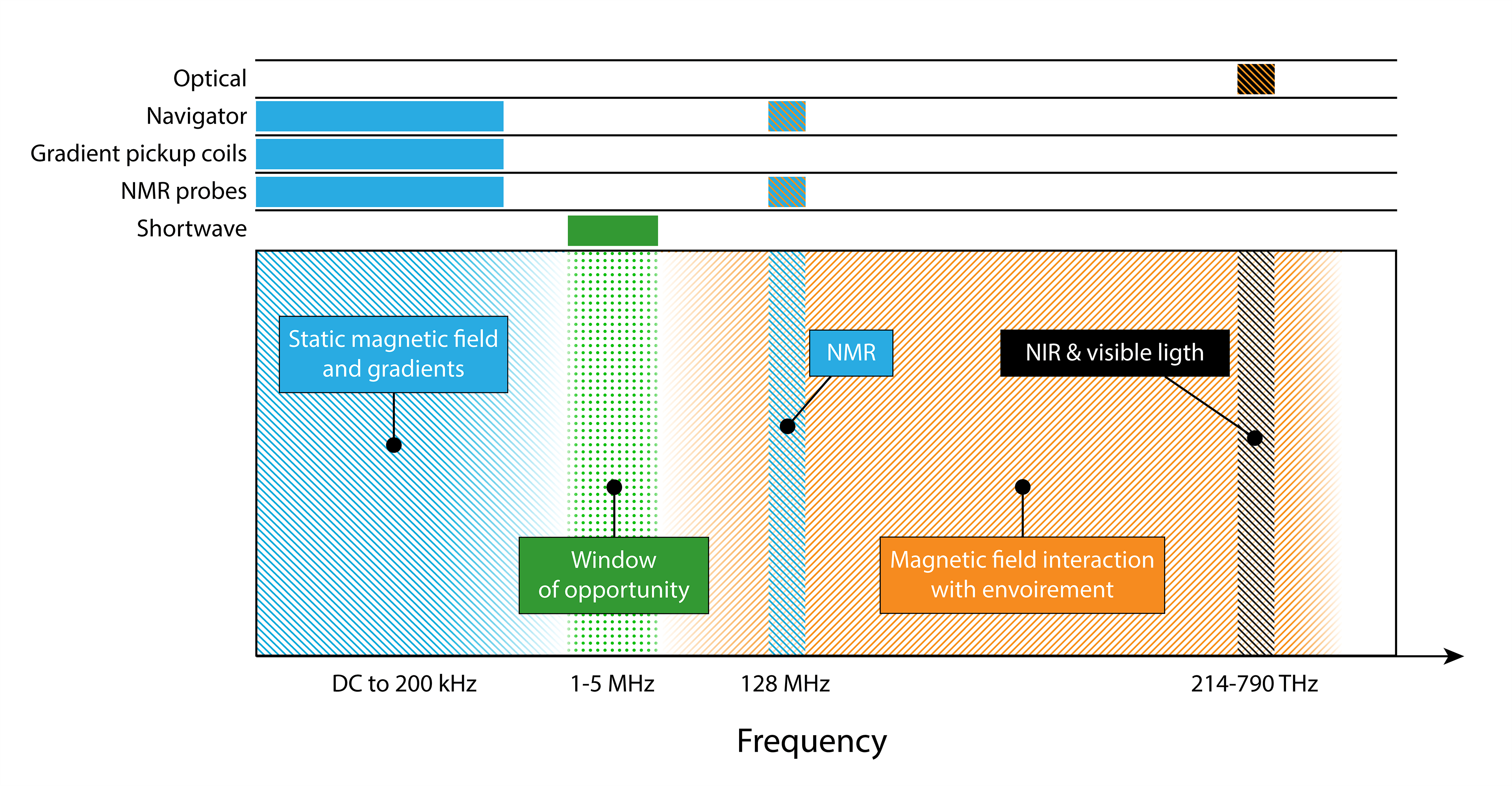
Shown
here is the magnetic frequency spectra found inside an MRI bore. In blue are
the frequencies that are occupied by the MRI machine and in orange is the
frequency range denoted in which magnetic fields interact with the environment,
such as human tissue and coil housing. As can be seen, the frequency range
of 1-5 MHz, neither does the MRI scanner
occupy this band nor interact with the environment, making it ideal for
independent and robust motion tracking.
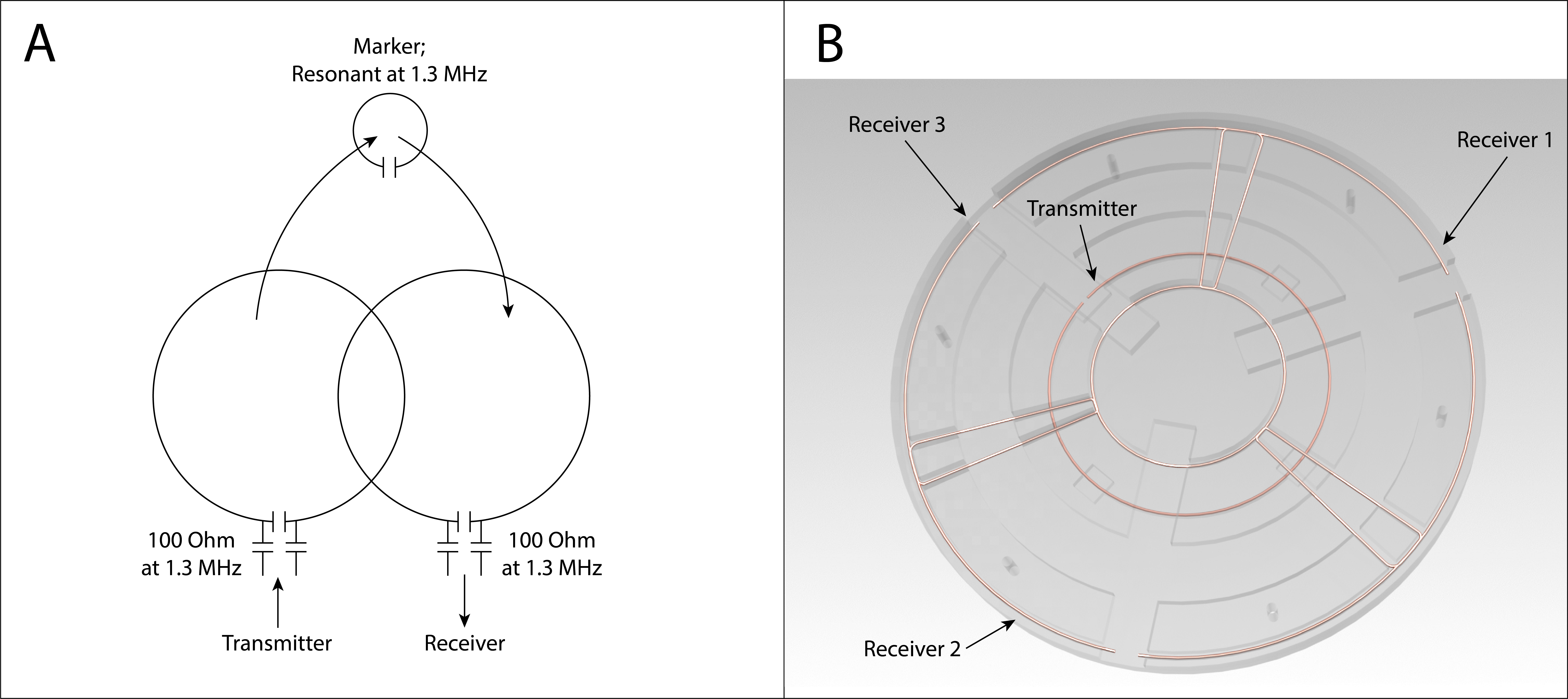
In section A is the principle show of the
short-wave tracking array. Both the transmitting and receiving coil are tuned
and matched to the operating frequency increasing the sensitivity by a significant
amount. Section B shows the conductor geometry for the utilized array. As can be
seen, a central transmitter loop is surrounded by three receiver ring segments.
The geometrical overlap decouples all coils in order to preserve the tuning and
matching characteristics.
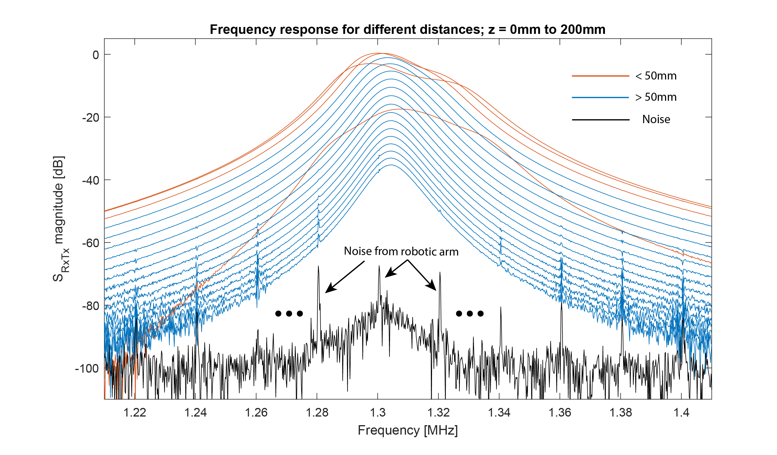
Shown here is the response of a receiver
channel given a marker in the centre of an array at a different distance. When the
marker gets close, the marker detunes the array, thereby broadening and decreasing
the signal strength. At distances greater than 50mm, the effect is strongly
reduced such that there is only one principal peak remaining, simplifying the
position estimation. The maximum distance in this plot is 200mm, demonstrating sufficient
signal even at large distances.
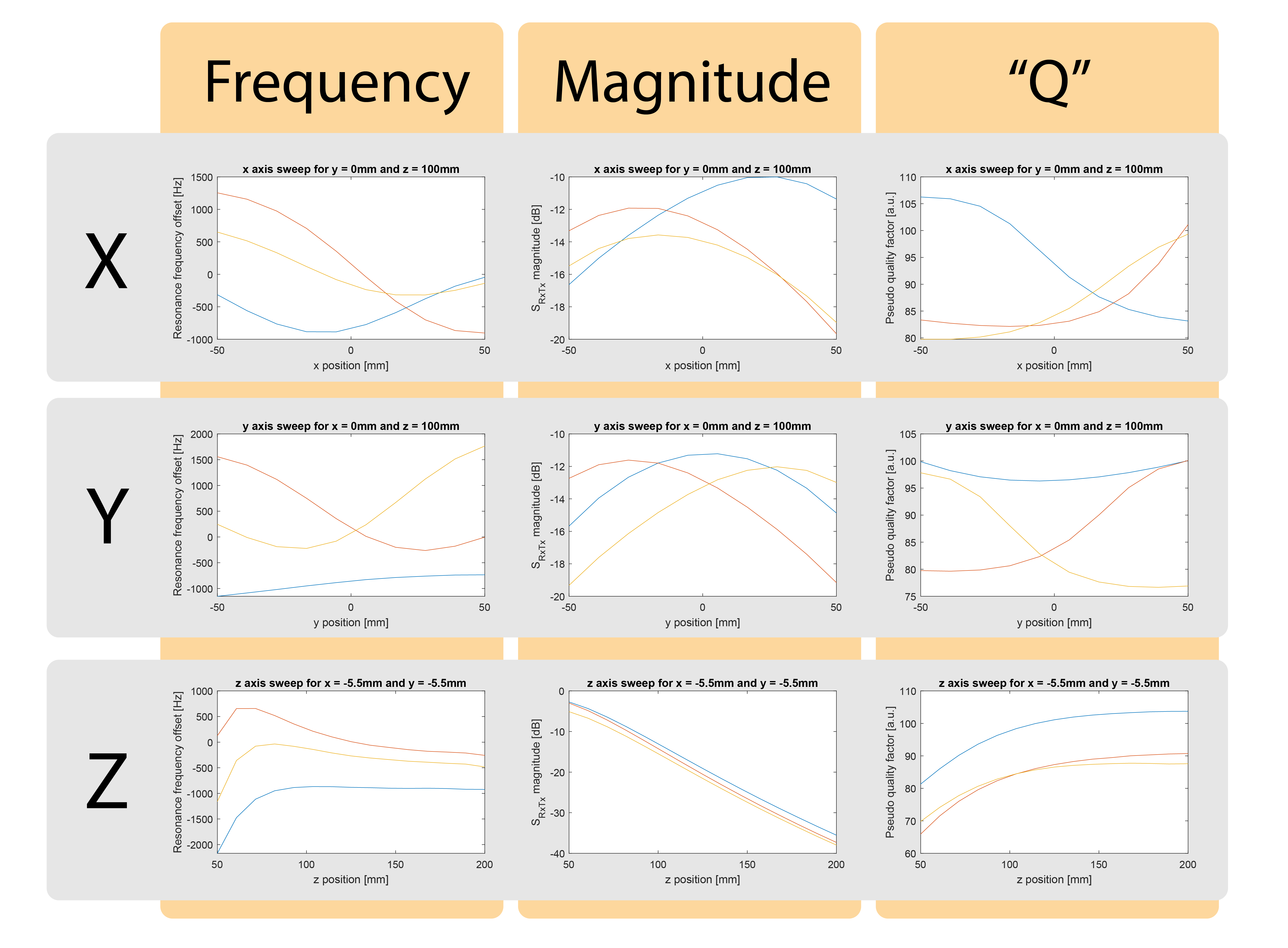
Given
frequency sweeps, as shown in Fig. 3, three parameters are extracted: the main
peak's frequency, magnitude, and quality factor. Shown here are those three
parameters for motion sweeps along the X-, Y- and Z-axis illustrating the
encoding of the position in those parameters.
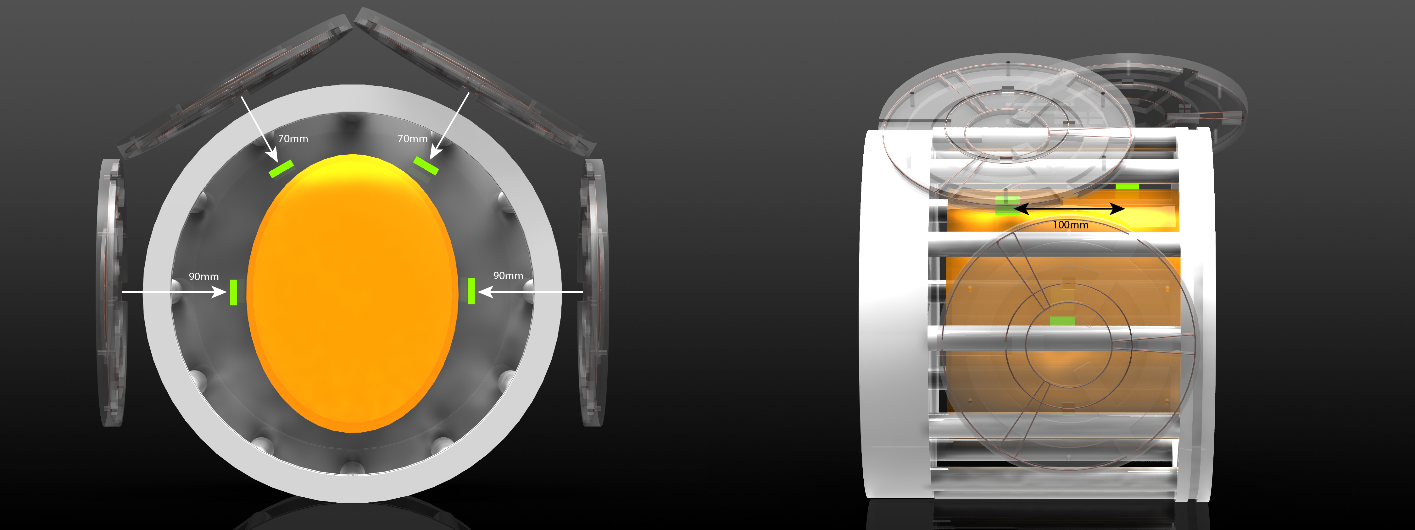
Shown
here is the four arrays short-wave tracking system utilized for the simulation
study. The green squares are the markers. In orange is an ellipse drawn with
roughly a 99 percentile envelope for head sizes. Even for a relatively large TR
birdcage, the distances from the array are well within the short-wave tracking
range.
DOI: https://doi.org/10.58530/2022/2053