2010
Mitigation of RF-induced heating on realistic deep brain stimulator lead trajectories by wireless sensor Q-matrix and parallel transmission1Physikalisch-Technische Bundesanstalt (PTB) Braunschweig and Berlin, Berlin, Germany, 2Athinoula A. Martinos Center for Biomedical Imaging, Massachusetts General Hospital, Boston, MA, United States, 3Harvard Medical School, Boston, MA, United States
Synopsis
Measurement-based pTx mitigations on realistic DBS lead trajectories are presented based on small, embedded sensors in the implant casing. Sensor Q-matrix measurements are performed and transmitted wirelessly from the implant to the pTx console. Three different DBS implant trajectories at four different locations have been tested showing successful pTx mitigations of RF induced heating in in-vitro. The methodology is conceptually appealing to be investigated further towards a safety strategy, where an implant communicates with a pTx capable MR scanner in order to improve MR safety and MR imaging performance.
Introduction
Parallel transmit (pTx) systems offer the necessary degrees of freedom to mitigate harmful RF-induced heating of deep brain stimulator (DBS) implants, while maintaining sufficient image quality for MRI.1–6 Translating these simulation based pTx mitigation approaches into clinical practice is challenging, however, due to subject specific E-field distributions, DBS electrodes and implant trajectories.6,7 Measurement-based mitigations using small and simple rms sensor readouts by acquiring a sensor Q-matrix (QS)8 showed proof of concept results that could be translated into a safety strategy where an implant communicates with a pTx capable MR scanner. The preliminary data was limited to long wire-like implants and simple geometries. In this work, we implemented and tested the QS-based pTx mitigation in a more realistic setting using: 1) a wireless implant hardware, 2) small diameter (2mm) leads, 3) sensors embedded in the casing and not at the lead tip, and 4) realistic DBS trajectories.Methods
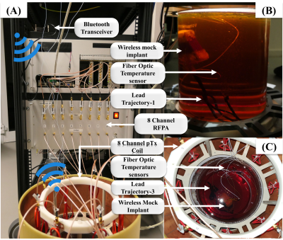
DBS implant modelsThree realistic DBS lead trajectories were used in the study and converted to a 3D printable CAD model7,10 (Figure-1). Afterwards, semi-rigid coaxial cables (diameter = 2 mm, uninsulated lead tip) were shaped around the 3D-printed (Ultimaker S5) trajectories, soldered to a SMA connector, and connected to home-built wireless hardware interface (Figure-2). No additional sensors were embedded on the lead cable, as this might be challenging to perform in realistic DBS leads. The RF-induced signal at the lead tip was entirely determined by the induced potential difference from inner to outer conductor at the lead tip and converted to a signal by the readout electronics inside the implant casing to determine the ‘sensor Q matrix’ QS8. Acquisition of QS and subsequent pTx mitigation was controlled and transmitted wirelessly.
Experimental Setup
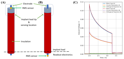
All experiments were performed using a pTx implant-safety testbed at 297MHz9, an 8-channel RF coil11 and a PVP filled cylindrical phantom. The mock implant with the connected DBS leads was fully immersed into the phantom (Figure-2B, C) (~4 cm from the top of the surface). Then, QS was acquired and the orthogonal projection (OP) method9 was used for pTx mitigation and compared to a circular polarized (CP) excitation. As a reference, an external fiber-optic temperature probe (CANSAS FBG-T8, imc Test & Measurement GmbH) was used, placed near the lead tip. Each DBS lead trajectory was tested at four different locations inside the cylindrical phantom. To explore the effect of the sensor position (inside the DBS lead vs. at the electrode’s tip), a CAT5 cable with uninsulated tip was placed into the phantom where one inner wire at the implant tip was connected to a rms sensor (Schottky diode), while at a neighboring wire the rectification circuit was placed before the ADC connection ~2 m away from the tip (Figure-3).
Results
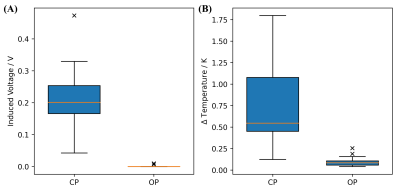
The results of the rms sensor location within the implant are depicted and compared in Figure-3. All three pTx excitation modes induce nearly the same signals at the tip independent of the rms sensor location for QS calculations. This indicates the possibility of placing the sensor in the implant casing, rather than embed them in the implant lead, which has stricter requirements for its maximum dimensions.The pTx mitigation results of all three implant trajectories at all four implant locations are shown in Figure-4. The induced RF signals from an overall input power of 9 W at the RF power amplifier output showed steady-state induced voltages between 43-473 mV for CP and <10 mV for the OP method for all implant locations (Figure-5). The corresponding temperature rises after one minute were 0.12-1.80 K for CP and 0.04-0.25 K for the OP method (Figure-5). For worst case mode pTx excitation, the highest tip temperature rise was 12.65 K after 1 minute of RF heating. Please note that the 9 W input power does not represent realistic power settings that are based on current local SAR limits.12 This power was only used to test the relative, not absolute, RF induced signals between different trajectories, implant locations and RF excitation modes and in practice higher RF powers are expected at the RF coil.
Discussion and Conclusion
Qs-based pTx mitigation was successfully demonstrated on realistic DBS implant trajectories, using wireless transmission, an implant lead diameter of only 2 mm and the sensor readout placed inside the implant casing without any rms sensors embedded in the implant leads. These measures do not only resemble a more realistic exposure setting, more importantly they make it much easier for implant manufacturers to integrate such sensors into their products. The results show that pTx mitigation can be successfully performed in this complex setting in-vitro and the methodology applied is conceptually appealing to be investigated further. In the next steps, more implant trajectories, sensor calibration, the determination of uncertainties and a communication workflow between implant and MR scanner, which is embedded into the native SAR safety concept, needs to be established and investigated.Acknowledgements
This work has received funding from the EMPIR programme co-financed by the Participating States and from the European Union's Horizon 2020 research and innovation program under grant number 17IND01 MIMAS.References
1. Eryaman Y, Akin B, Atalar E. Reduction of implant RF heating through modification of transmit coil electric field. Magn Reson Med. 2011;65(5):1305-1313. doi:10.1002/mrm.22724
2. Eryaman Y, Guerin B, Akgun C, et al. Parallel transmit pulse design for patients with deep brain stimulation implants. Magn Reson Med. 2015;73(5):1896-1903. doi:10.1002/mrm.25324
3. McElcheran CE, Yang B, Anderson KJT, Golenstani-Rad L, Graham SJ. Investigation of parallel radiofrequency transmission for the reduction of heating in long conductive leads in 3 Tesla magnetic resonance imaging. PLoS ONE. 2015;10(8). doi:10.1371/journal.pone.0134379
4. McElcheran CE, Yang B, Anderson KJT, Golestanirad L, Graham SJ. Parallel radiofrequency transmission at 3 tesla to improve safety in bilateral implanted wires in a heterogeneous model. Magn Reson Med. 2017;78(6):2406-2415. doi:10.1002/mrm.26622
5. Eryaman Y, Kobayashi N, Moen S, et al. A simple geometric analysis method for measuring and mitigating RF induced currents on Deep Brain Stimulation leads by multichannel transmission/reception. NeuroImage. 2019;184:658-668. doi:10.1016/J.NEUROIMAGE.2018.09.072
6. Guerin B, Angelone LM, Dougherty D, Wald LL. Parallel transmission to reduce absorbed power around deep brain stimulation devices in MRI: Impact of number and arrangement of transmit channels. Magn Reson Med. 2020;83(1):299-311. doi:10.1002/mrm.27905
7. Guerin B, Iacono MI, Davids M, Dougherty D, Angelone LM, Wald LL. The ‘virtual DBS population’: five realistic computational models of deep brain stimulation patients for electromagnetic MR safety studies. Phys Med Biol. 2019;64(3):035021. doi:10.1088/1361-6560/aafce8
8. Silemek B, Seifert F, Petzold J, et al. Rapid safety assessment and mitigation of radiofrequency induced implant heating using small root mean square sensors and the sensor matrix Qs. Magn Reson Med. n/a(n/a). doi:10.1002/mrm.28968
9. Winter L, Silemek B, Petzold J, et al. Parallel transmission medical implant safety testbed: Real-time mitigation of RF induced tip heating using time-domain E-field sensors. Magn Reson Med. 2020;84(6):3468-3484. doi:https://doi.org/10.1002/mrm.28379
10. Guerin B, Serano P, Iacono MI, et al. Realistic modeling of deep brain stimulation implants for electromagnetic MRI safety studies. Phys Med Biol. 2018;63(9):095015. doi:10.1088/1361-6560/aabd50
11. Seifert F, Pfeiffer H, Mekle R, Waxmann P, Ittermann B. 7T 8-Channel PTx Head Coil with High B1+ Efficiency Optimized for MRS. In: 24th Annual Meeting of ISMRM. ; 2016:3545.
12. International Electrotechnical Commission (IEC): IEC 60601–2-33:2010+AMD1:2013+AMD2:2015 CSV: Medical electrical equipment — particular requirements for the basic safety and essential performance of magnetic resonance equipment for medical diagnosis, Edition 3.2.2015
Figures

Figure-1: 3D printed lead trajectories and fabricated leads from 2 mm diameter coaxial semi-rigid wire (DA10070, Elspec GmbH). The leads were insulated apart from the lead tip and soldered to an SMA connector, which was connected to the wireless transmission hardware.

Figure-2: Photographs of the experimental setup. (A) 8-channel pTx system connected to an 8-channel 7T RF coil at 297 MHz.9 A Bluetooth-Low-Energy (BLE) transceiver (cc2640R2, Launchpad, TI) is connected to the testbed. This transceiver communicates with the implant using a BLE wireless link. (B) Mock implant with DBS lead trajectory-1 immersed in the cylindrical phantom with the RF coil removed. (C) Top-view from DBS lead trajectory-3 inside the cylindrical phantom and RF coil. Fiber optic temperature probes are positioned at the lead tips.

Figure-3: Schematic of the rms sensor location (A) at the implant lead tip and (B) at the readout electronics. (C) RF induced lead tip signals for the same lead trajectory and for different RF excitation scenarios derived from the measured QS and rms sensor locations (A, solid line) and (B, dashed line). Please note that even though the rms sensor in (B) is located 218 cm away from the implant tip, the sensing location for the RF induced signal is at the implant tip and only rectified at the implant electronics.

Figure-4: RF induced heating from three DBS trajectories at four implant locations per trajectory. Induced voltages (dashed lines) and their corresponding temperature rises (solid lines). (A) Trajectory-1 induced voltages: 0.13-0.47 V, for CP and 0 V for OP. The temperature rises: 0.30-1.80 K for CP and 0.04-0.25 K for OP. (B) Trajectory-2 induced voltages: 0.04-0.28 V for CP and 0-0.01 V for OP. Temperature rises: 0.12-0.65 K, for CP and 0.07-0.19 K for OP. (C) Trajectory-3 induced voltages for CP: 0.18-0.33 V and 0.01 V for OP. Temperature rises: 0.50-1.60 K for CP and 0.06-0.09 K for OP.

Figure-5: Summary of A) the induced lead tip voltages and B) lead tip temperatures for all implant trajectories, implant locations and RF excitation modes CP and OP. Most of the induced voltages for CP range between 43-330 mV with a median of 200 mV. There is one outlier at 473 mV. For the OP, the median is zero and there are two outliers at 7 and 10 mV. Temperature rises for the CP range between 0.12-1.80 K with a median at 0.54 K, while for the OP 0.04-0.16 K with a median at 0.09 K were observed including two outliers at 0.19 K and 0.25 K.