2009
Wireless reference implant and communication methodology to assess and investigate RF safety and pTx mitigation strategies for AIMDs1Physikalisch-Technische Bundesanstalt (PTB) Braunschweig and Berlin, Berlin, Germany
Synopsis
Parallel transmission (pTx) systems can substantially improve the RF-safety of active implantable medical devices (AIMDs) in MRI. Here, a wireless reference implant is presented to test pTx mitigation strategies of RF induced implant heating. It is demonstrated that the proposed hardware and communication workflow can measure the sensor Q matrix and use this information to mitigate RF induced heating. The proposed setup enables conceptualization and further testing of a safety strategy relying on an implant communicating with a pTx capable MRI to improve RF safety without major restrictions in MR imaging performance.
Introduction
RF safety of active implantable medical devices (AIMDs) and MR image quality in the presence of implants can be substantially improved with parallel transmission (pTx) systems.1–6 Small rms sensors embedded in AIMDs could exploit these benefits by using pTx for improved measurement based, subject specific RF safety.7 Such concepts require the AIMD to communicate wirelessly with the pTx-capable MR scanner but the wireless solutions presented so far do not meet the requirements for such application.8–10 Here, we propose a Bluetooth low energy (BLE)-based wireless implant hardware and communication workflow suitable to investigate a variety of pTx mitigation scenarios.Methods
Implant DesignHardware
The basic schematic of the electronic circuit and the casing of the mock implant is shown in Figure-1. A BLE version 5.2 system on chip (SoC) (cc2652RB, Texas Instruments) is used with a 2.4 GHz antenna. Prior to the 12-bit ADC input of the SoC, a low-pass filter (LPF) and a Schottky diode are implemented. This allows sampling of rms signals that are induced at the implant lead to acquire the sensor Q-matrix (QS).7 Power is provided by a Li-ion battery including a battery protection and a DC/DC converter module.
Firmware
The firmware has all BLE core requirements and can be wirelessly programmed using a secured BLE over-the-air download. To sample QS for an 8-channel RF coil,7 the ADC was programmed to 13 kHz sampling frequency and a total acquisition time of 56 ms. The samples are written to the RAM of the SoC.
Software and pTx mitigation
A python-based software including a GUI was implemented to run on a computer and communicate with the implant. The software uses serial commands via a USB/UART interface to send to a BLE server (cc2640R2 Launchpad, Texas Instruments). Pulse detection, extraction of QS, and pTx mitigation are performed in this software. For pTx mitigation, the orthogonal projection (OP) method was used.11
Communication workflow
The communication workflow for pTx mitigation is depicted in Figure-2. A wireless “RF start” trigger was implemented to synchronize the pTx transmission and reception of the QS signals and lower the burden for SoC RAM and battery power. During QS acquisition, BLE connection parameters are set to the fastest rates to reduce timing uncertainties. The connection interval was 7.5-10 ms without any slave latency between master and slave.12 For the QS acquisition, which has a probability of not inducing any signals for some pTx channel combinations7, 4-additional 200µs long (forward and reverse circularly polarized) RF pulses are inserted at the start and at the end of the pulse train.
pTx experiments
Experiments have been performed using an 8-channel pTx safety testbed system at 297MHz11 and an 8-channel 7T RF coil12 .
Wireless transmission vs. wired sampling
A long (2.18m) straight coaxial cable was used and inserted into the PVP filled phantom as depicted in Figure-1C. At a sufficiently long distance to the RF coil, a manual switch was implemented routing the signal either to the wireless implant hardware or via a LPF (SLP- 1.9+, Mini-Circuits) and Schottky diode to the 14-bit ADC of the testbed. Then, the corresponding QS acquisitions and pTx mitigations were evaluated and compared.
pTx mitigation with fully immersed implant
To test a more realistic setting, the wireless implant connected to a 17.7cm long lead was fully immersed into the phantom at five different locations and orientations and QS acquisitions and subsequent pTx mitigation were performed.
Results
The results of 12 wireless measurements of the QS are shown in Figure-3, where the timing uncertainty of 20 ms (2 x 10ms connection interval) was successfully corrected (Figure-3b). The calculated pTx mitigation vector for the OP varied with a maximum of ±2% in amplitudes and phases (Figure-3c-d).The measured QS show similar results in both wired and wireless acquisitions and the corresponding pTx mitigations were successful for both 12-bit and 14-bit sampling (Figure-4). The absolute values of the wireless configuration were higher because the cut-off of the LPF is tuned and matched14,15 to the QS acquisitions and different from the commercial LPF in the testbed.
The fully immersed implant was successfully communicating within a range of 5m, which is sufficient for application in MR conditions. The orthogonal projection method was successfully mitigating the RF induced currents on the implant lead for all tested implant positions compared to a circular polarized and worst-case excitation (Figure-5). The highest detectable signal for OP at position 2 was still 25 times lower than CP and 67 times lower than worst case mode.
Discussion and Conclusion
A BLE based wireless implant was developed and tested to assess the safety and mitigation of RF induced currents on implant leads. BLE is already regulated16 and implemented in commercially available AIMDs. This wireless implant enables the conceptualization and further testing of a novel safety strategy of “smart” medical implants that communicate with a pTx capable (≥2 transmit channels) MR scanner to improve RF safety without major restrictions in MR imaging performance.Acknowledgements
This work has received funding from the EMPIR programme co-financed by the Participating States and from the European Union's Horizon 2020 research and innovation program under grant number 17IND01 MIMAS.
References
1. Eryaman Y, Akin B, Atalar E. Reduction of implant RF heating through modification of transmit coil electric field. Magn Reson Med. 2011;65(5):1305-1313. doi:10.1002/mrm.22724
2. McElcheran CE, Yang B, Anderson KJT, Golenstani-Rad L, Graham SJ. Investigation of parallel radiofrequency transmission for the reduction of heating in long conductive leads in 3 Tesla magnetic resonance imaging. PLoS ONE. 2015;10(8). doi:10.1371/journal.pone.0134379
3. McElcheran CE, Yang B, Anderson KJT, Golestanirad L, Graham SJ. Parallel radiofrequency transmission at 3 tesla to improve safety in bilateral implanted wires in a heterogeneous model. Magn Reson Med. 2017;78(6):2406-2415. doi:10.1002/mrm.26622
4. Eryaman Y, Guerin B, Akgun C, et al. Parallel transmit pulse design for patients with deep brain stimulation implants. Magn Reson Med. 2015;73(5):1896-1903. doi:10.1002/mrm.25324
5. Eryaman Y, Kobayashi N, Moen S, et al. A simple geometric analysis method for measuring and mitigating RF induced currents on Deep Brain Stimulation leads by multichannel transmission/reception. NeuroImage. 2019;184:658-668. doi:10.1016/J.NEUROIMAGE.2018.09.072
6. Guerin B, Angelone LM, Dougherty D, Wald LL. Parallel transmission to reduce absorbed power around deep brain stimulation devices in MRI: Impact of number and arrangement of transmit channels. Magn Reson Med. 2020;83(1):299-311. doi:10.1002/mrm.27905
7. Silemek B, Seifert F, Petzold J, et al. Rapid safety assessment and mitigation of radiofrequency induced implant heating using small root mean square sensors and the sensor matrix Qs. Magn Reson Med. n/a(n/a). doi:10.1002/mrm.28968
8. Acikel V, Silemek B, Atalar E. Wireless control of induced radiofrequency currents in active implantable medical devices during MRI. Magn Reson Med. Published online November 25, 2019:mrm.28089. doi:10.1002/mrm.28089
9. Silemek B, Acikel V, Oto C, et al. A temperature sensor implant for active implantable medical devices for in vivo subacute heating tests under MRI. Magn Reson Med. 2018;79(5). doi:10.1002/mrm.26914
10. Özen AC, Silemek B, Lottner T, Atalar E, Bock M. MR safety watchdog for active catheters: Wireless impedance control with real‐time feedback. Magn Reson Med. Published online January 21, 2020:mrm.28153. doi:10.1002/mrm.28153
11. Winter L, Silemek B, Petzold J, et al. Parallel transmission medical implant safety testbed: Real-time mitigation of RF induced tip heating using time-domain E-field sensors. Magn Reson Med. 2020;84(6):3468-3484. doi:https://doi.org/10.1002/mrm.28379
12. Core Specification 5.2. Bluetooth® Technology Website. Accessed March 4, 2021. https://www.bluetooth.com/specifications/specs/core-specification/
13. Seifert F, Pfeiffer H, Mekle R, Waxmann P, Ittermann B. 7T 8-Channel PTx Head Coil with High B1+ Efficiency Optimized for MRS. In: 24th Annual Meeting of ISMRM. ; 2016:3545.
14. Meier K, Burkhardt M, Schmid T, Kuster N. Broadband calibration of E-field probes in lossy media. IEEE Trans Microw Theory Tech. 1996;44(10):1954-1962. doi:10.1109/22.539955
15. Smith GS. Analysis of Miniature Electric Field Probes with Resistive Transmission Lines. IEEE Trans Microw Theory Tech. 1981;29(11):1213-1224. doi:10.1109/TMTT.1981.1130534
16. FCC Dedicates Spectrum Enabling Medical Body Area Networks. Federal Communications Commission. Published December 13, 2015. Accessed February 26, 2021. https://www.fcc.gov/document/fcc-dedicates-spectrum-enabling-medical-body-area-networks
Figures
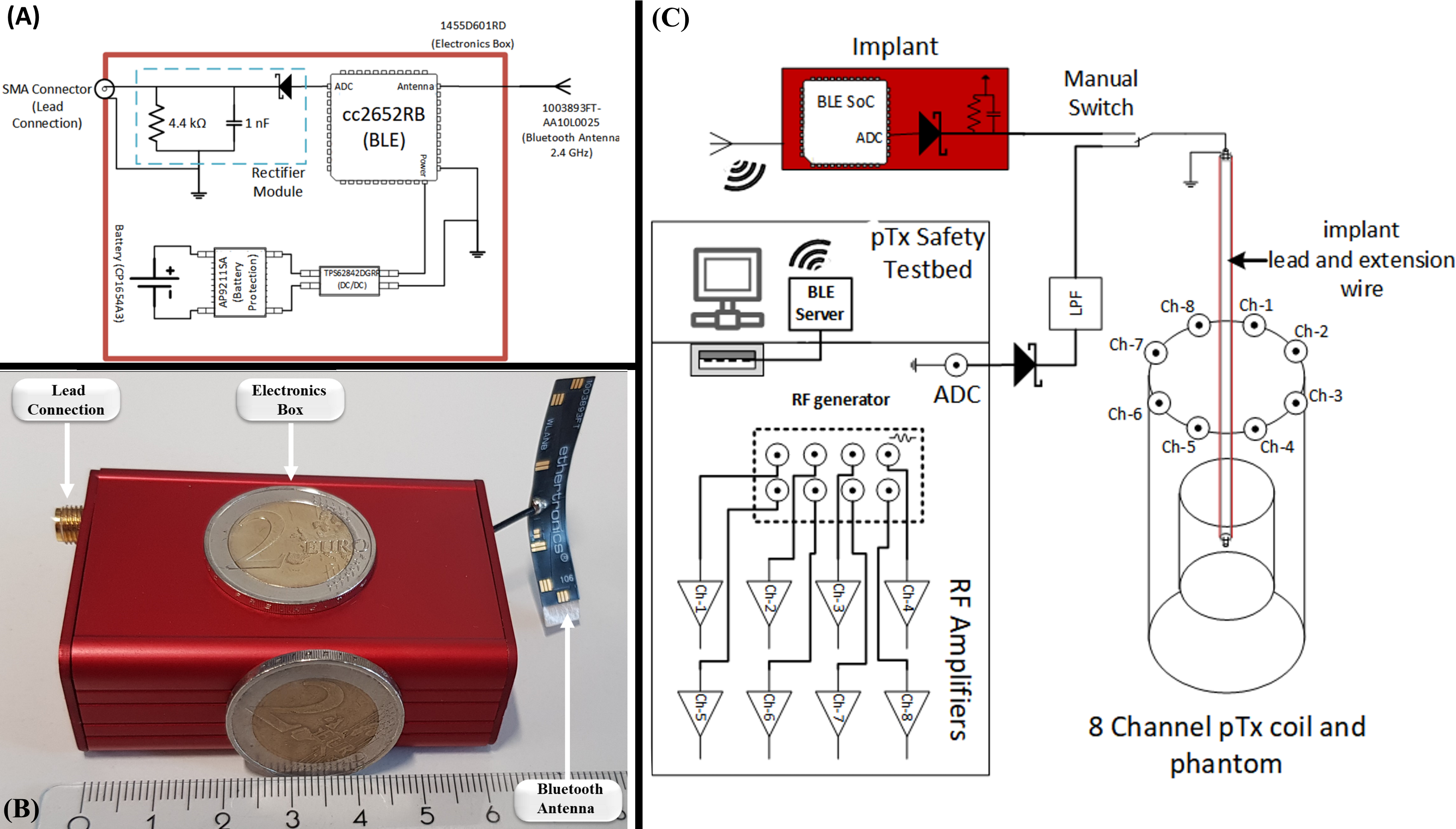
Figure-1: (A) Schematic of the reference implant circuit. The battery (CP1654A3, Varta) powered implant has a battery protection circuit and DC/DC converter powering the BLE SoC (cc2652RB, TI). For the RF power detection circuit, a Schottky diode (MMDL101T1G, ON semi) is connected to the ADC of the SoC with a LPF (fcut-off = 37 kHz). (B) Photograph of the assembled electronics inside the aluminum implant case (60×45×25) cm³ with BLE antenna and SMA connector to attach implant leads. (C) Schematic representation of the wireless vs. the wired test setup using the pTx testbed11
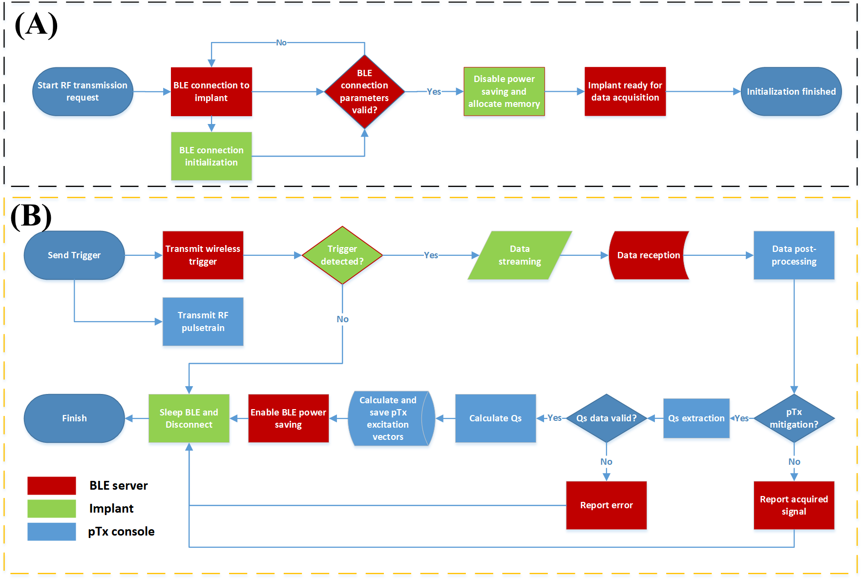
Figure-2: Flowchart of the wireless communication between pTx console, BLE server and reference implant that is used for pTx mitigation. (A) Initialization steps to establish the communication between pTx console, BLE server and reference implant. (B) Communication workflow for pTx mitigation consisting of the QS acquisition and corresponding calculations and readout of the OP excitation vectors. At this stage, data streaming of the measured pulse train for QS acquisition is performed and the pTx console calculates the QS.
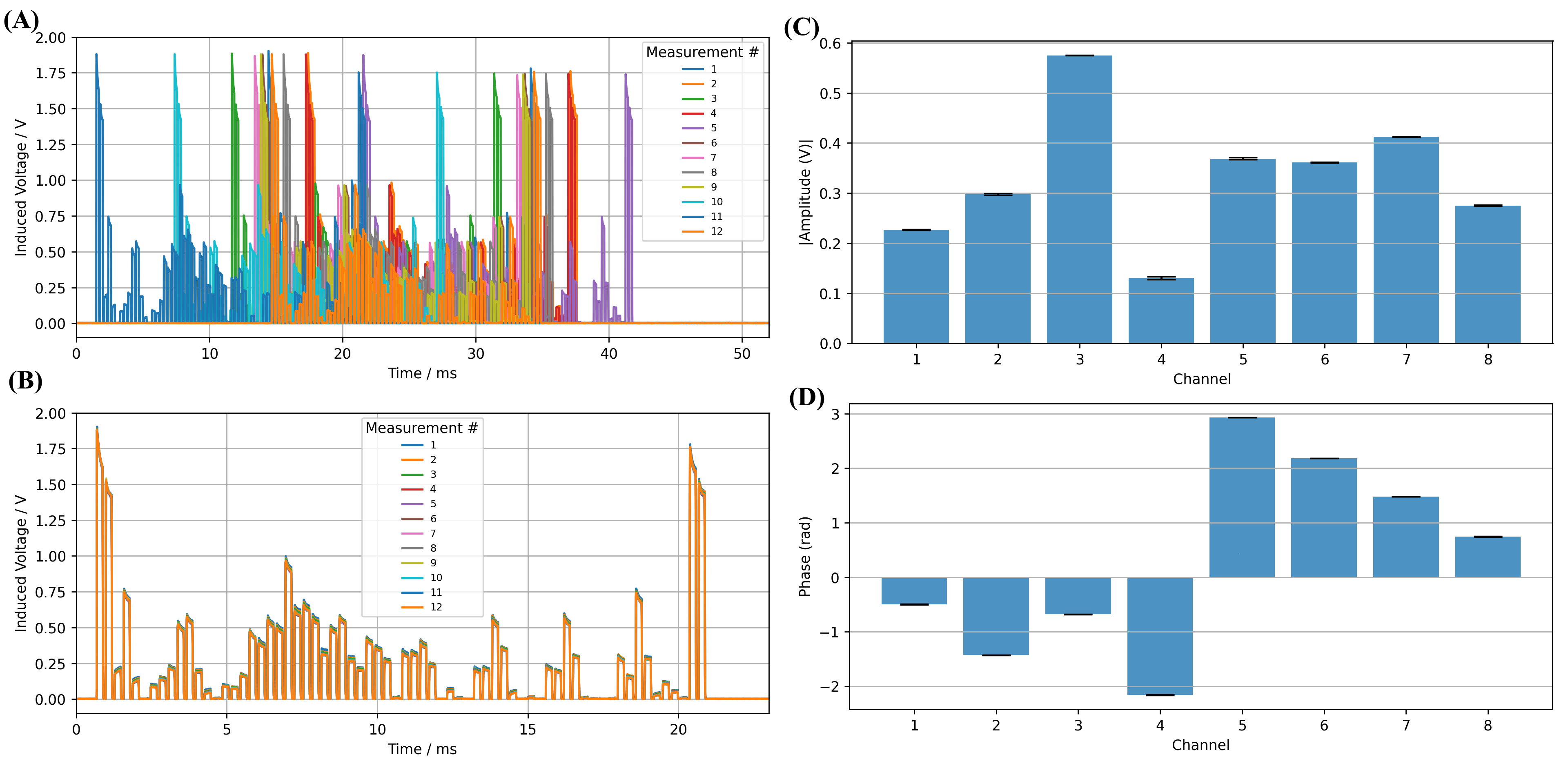
Figure-3: Results of 12x acquisitions of the QS using the wireless implant. (A) Uncorrected pulse train for the same QS acquisition in the corresponding sampling interval. The timing uncertainty of about 20 ms can be observed. (B) Corrected signals of the same pulse train as shown in panel A. The timestamp pulses at the start and the end of the sequence were used for correction. (C) Amplitudes and (D) phases of a pTx mitigation calculated using QS from (B) and corresponding error bars. Variations in calculated pTx mitigation pulses for the OP mode were less than <±2% (amplitudes and phases).
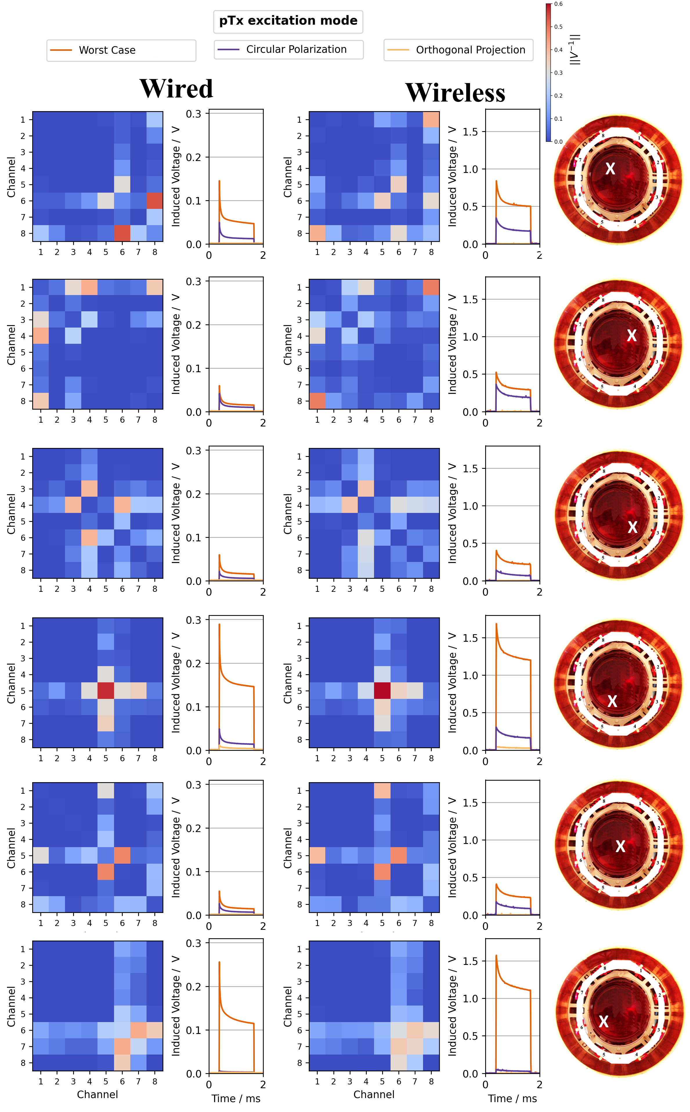
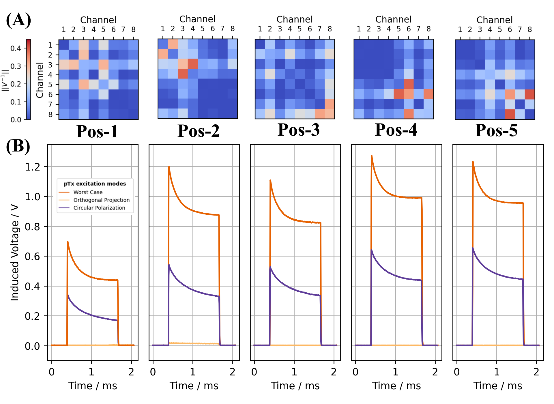
Figure-5: Results of wireless QS acquisitions and pTx mitigation of the fully immersed reference implant with an implant lead length of 17,7cm from 5 different implant locations. The fully immersed implant communicated wirelessly with the pTx console and software interface. At each position the RF-induced currents at the lead tip could be reduced substantially in the orthogonal projection mode based on the QS data sampled and communicated by the wireless implant.