2007
Novel Compact Dual-Band E-Field Generator for MR Safety Testing of Active Implantable Medical Devices1IT'IS Foundation, Zurich, Switzerland, 2Department of Information Technology and Electrical Engineering, ETH Zurich, Zurich, Switzerland
Synopsis
A compact dual-band E-field generator for MRI implant safety testing has been developed to produce diverse, well-defined tangential incident E-fields along defined implant test routings for efficient validation of the transfer function of AIMD. The MITS medical implant test system consists of two pairs of electrodes whose relative amplitude and phase are controlled to create E-field conditions at the frequencies corresponding to 1.5 T and 3 T MRI. Simulations of different exposure settings were validated by measurements of the resulting field distributions with an E-field vector probe along the routing paths.
Introduction
The compact dual-band electric (E-)field generator is designed to produce well-defined tangential E-field conditions along the lead of an elongated active implantable medical device (AIMD), to enable robust validation of the transfer function1. Traditional validation methods induce the E-field in a phantom using a B1+ field generated by a radiofrequency (RF) resonator with high power amplifiers. Recently, an E-field resonator was proposed2 to generate high strength E-fields with fixed distributions inside a rectangular gel phantom clad with conductive material for ASTM-like tests. Here, we combine the concepts we developed for the Medical Implant Test System (MITS) high-field resonator1 and the test field diversity (TFD) approach3 to directly induce programmable E-field patterns in a cylindrical phantom through two pairs of curved electrodes in direct contact with the phantom liquid. This makes the MITS more compact than a birdcage-type RF-coil (e.g., MITS1.5/3.0), reduces the amplifier power requirements, and increases control of tangential E-fields induced along defined routings.Methods
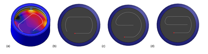
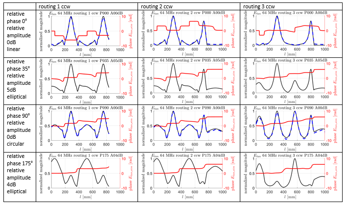
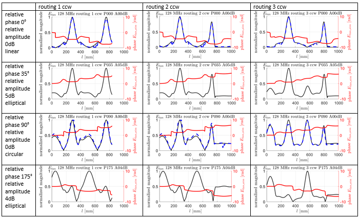
To create diverse incident field conditions along the AIMD lead, an E-field generator was designed consisting of a cylindrical phantom with two pairs of integrated curved electrodes arranged orthogonally to each other, each pair being differentially fed and individually controlled (Figure 1 (a)). The E-fields are induced inside a cylindrical phantom at the frequencies corresponding to 1.5 T and 3 T clinical magnetic resonance systems, i.e., 64 MHz and 128 MHz, respectively. The phantom of the dual-band E-field generator has the same dimensions as the cylindrical TFD phantom3 of the MITS1.5/3.01 (ZMT Zurich MedTech AG, Switzerland; ZMT). By varying the relative phase and amplitude between the two orthogonal channels, different incident field conditions can be achieved along the standard lead routings3. The two remaining electrodes are set with a phase shift of 180° to the primary orthogonal electrodes.Initial simulations of the tangential E-field in high conductivity liquid (εr = 78 and σ = 0.47 S/m)1 were carried out using the electromagnetic finite-difference time domain (EM-FDTD) solver of Sim4Life (ZMT). Implant routings were defined as in 3, and the counter-clockwise variant was chosen for each routing (Figure 1(b-d)). The defined test routings ensure a minimum distance of 5 cm to the phantom boundaries and 10 cm between the lead segments. With this setup, lead lengths of up to 110 cm can be validated. The corresponding E-field distributions for linear, circular, and two ellipsoidal polarizations (relative phase 35° and amplitude 5 dB; relative phase 175° and amplitude 4 dB) are shown in Figures 3 and 4, respectively. Field maps of the prototype were obtained with an E-field vector probe at linear and circular polarizations, and the tangential E-fields along the sample routings were extracted to validate the simulations. The measurements and simulations are in agreement within the estimated measurement confidence interval of 0.8 dB (k = 1).
Results
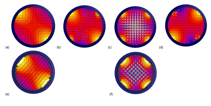
The induced E-fields corresponding to a circular and a linear polarization are displayed in Figure 2(a) and (c), respectively, and for the two ellipsoidal polarizations in Figure 2(b) and (d), respectively, where both the root mean square field amplitude and the polarization are visualized. Polarizations are referenced to the center of the phantom, since the polarization varies radially. The magnitude of the E-field is highest between adjacent electrodes.Figures 3 and 4 show the resulting tangential fields extracted along the three predefined routings at 1.5T (64 MHz) and 3T (128 MHz), respectively, as well as the validation measurements. By using only a few routings within the phantom, diverse incident field conditions can be realized for the validation of the transfer function.Conclusion
The dual-band E-field generator successfully induces well-defined, diverse incident field conditions along selected implant routings of up to 110 cm in length in an integrated phantom. The design supports efficient validation of the transfer function of AIMD without the need of high-power amplifiers, active cooling systems, and an anechoic chamber. The compact design can be set up on a standard lab bench.Acknowledgements
No acknowledgement found.References
1. ISO. Assessment of the safety of magnetic resonance imaging for patients with an active implantable medical device, Technical Report 10974:2018, International Organization for Standardization, Geneva, Switzerland.
2. Wang Y, Song S, Zheng J, et al., A Novel Device Model Validation Strategy for 1.5- and 3-T MRI Heating Safety Assessment, IEEE Transactions on Instrumentation and Measurement, 2020; 69(9); 6381-6389
3. Yao A, Zastrow E, Neufeld E, et al. Novel test field diversity method for demonstrating magnetic resonance imaging safety of active implantable medical devices. Phys Med Biol. 2020;65(7):075004.
Figures