2006
Wireless Power Harvesting of the B1 Field During MR Image Acquisition for Pulse Charging of MR-Compatible Batteries1Medical Physics Graduate Program, Duke University, Durham, NC, United States, 2Brain Imaging and Analysis Center, Duke University, Durham, NC, United States, 3GE Healthcare, Aurora, OH, United States
Synopsis
A 4-channel power harvesting coil array was developed to allow the energy emitted from RF transmit pulses within the scanner bore during imaging to be converted into DC voltage pulses for recharging MR-compatible batteries, regardless of the scan parameters or imaging pulse sequence. Proof-of-concept experiments in a phantom show that this power harvesting coil array was able to provide energy to a battery during GRE image acquisition for various flip angles and additionally during GRE-EPI, DTI, and MPRAGE image acquisitions.
Introduction
Wireless RF coil technologies for wireless data transmission from/to the MRI scanner bore have recently been proposed to improve image quality and patient comfort, reduce the number of bulky cables, and lower the cost and complexity of MRI systems, for applications such as wireless: localized B0 shimming1,2, physiological monitoring2,3,4, Q-spoiling5,6, and MRI data transmission7,8. The wireless devices used in these applications are commonly powered with non-magnetic rechargeable batteries placed within the scanner bore. However, battery charge time or regularly swapping in new batteries can limit patient scan time and interrupt the clinical workflow. To address this limitation, wireless power harvesting (WPH) has been investigated as an alternative power source9,10 where the electromagnetic energy from the RF transmit pulses for imaging is converted into useful power for wireless devices, which requires no scanner modifications in contrast to other wireless power transfer methods11,12. WPH utilizes “harvesting” coils to capture the transmit B1 RF energy and an AC-DC converter to rectify the acquired voltage. Unfortunately, applying the rectified DC voltage directly to wireless devices is challenging as the amplitude and smoothness (i.e., temporal stability) of the voltage depend on the flip angle, B1 transmit power, and TR9,10. Voltage fluctuations can be reduced with additional electronics or filtering, but they cannot be fully eliminated for long-TR scans, whereas over-smoothing would reduce the amount of harvested power for short-TR scans, which could shutoff or damage wireless devices and reduce efficiency, respectively. Here, we address these limitations by using an array of harvesting coils to wirelessly recharge an in-bore battery during image acquisition via unsmoothed regulated DC pulses. Pulse-charging batteries within the scanner bore is a novel and promising charging technique, which allows for high-efficiency battery charging regardless of the pulse sequence or scan parameters.Methods
First, four 10-cm diameter harvesting RF coils were constructed to be resonant at the Larmor frequency and arranged into a 1x4 array (Fig.1A) with the coil outputs connected either in series (Fig. 1B), parallel (Fig. 1C), or a series/parallel combination (Fig. 1D) to achieve higher RF voltages during low B1 field (e.g., flip angles < 20o) MR scans, a more balanced power delivery to multiple in-bore batteries during high B1 field MR scans (e.g., flip angles > 50o), or a combination of both, respectively. Second, a full-wave AC-DC converter10 (Fig. 1, purple) was added to each output to rectify the induced RF voltages. Finally, a voltage regulator was added in series with the battery (Fig. 1, green) to prevent the unsmoothed DC pulses from exceeding 3.9 V, which could otherwise damage the battery (Vbatterymax = 4.2 V).Two proof-of-concept experiments were performed in a 3T scanner to verify that the 4-channel harvesting coil array could pulse-charge a battery for multiple scan parameters and pulse sequences. First, multi-echo gradient-echo (GRE) images were acquired on a water phantom with a 48-channel head coil array using flip angles between 5o and 90o for each of the three coil output configurations. Second, images were acquired over a 10-minute duration using various pulse sequences: GRE, GRE echo-planar imaging (GRE-EPI) typically used for fMRI, diffusion tensor imaging (DTI), and T1-weighted MPRAGE, with the harvesting coils in the series configuration, to demonstrate their ability to harvest power regardless of the pulse sequence and apply the harvested energy to recharge the battery. During these experiments, the input RF voltages, AC-DC converted pulses, and DC power delivered to the battery were measured using an oscilloscope.
Results
The 4-channel harvesting coil array was able to provide unsmoothed DC pulses (0.57 to 0.95 ms pulse width) to charge the battery for various flip angles during GRE image acquisition (Fig. 2A) for each of the coil output configurations (Fig. 2B). Additionally, the harvested energy applied to recharge the battery during the GRE, GRE-EPI, DTI, and MPRAGE pulse sequences (Fig. 3) after 10 minutes was 0.7, 6.6, 9.0, and 2.5 mJ, respectively (Fig. 4).Discussion and Conclusion
This work demonstrates that the 4-channel harvesting coil array can reliably harvest power during image acquisition regardless of the pulse sequence or scan parameters. When the B1 transmit power is low (for flip angles < 20o), a series configuration is required, otherwise the induced voltage is too low to be applied to the battery. When the B1 transmit power is high (for flip angles > 50o), a series/parallel configuration with multiple batteries can be used to avoid power loss to currently available components required for harvesting. For very large flip angles (> 60o; green region in Fig. 2B), the B1 transmit power is limited by the scanner to prevent damaging the RF receive coil array electronics and instead the RF pulse duration is increased. Since the DC pulses applied to the battery are unsmoothed, there is no impact in power harvested when changing the TR or number of slices, in contrast to a previously proposed power harvesting method9,10. Expanding upon these preliminary results, we envision adding a wireless module and voltage-controlled switches that could wirelessly change the coil configuration depending on the flip angle or RF pulse type (e.g., fat saturation) to optimize efficiency via control signals from the MRI scanner trigger6.Acknowledgements
This work was in part supported by GE Healthcare and grants R01 NS075017 and R01 EB028644 from the National Institutes of Health.
References
1. Cuthbertson J et al. A 4-channel iPRES-W AIR coil array for simultaneous MR image acquisition and wirelessly-controlled localized B0 shimming of the spinal cord. Proc ISMRM. 2019;27:1489.
2. Cuthbertson J et al. Dual-stream iPRES-W head coil array for MR imaging, wireless respiratory tracking, and wireless localized B0 shimming. Proc ISMRM. 2020;28:1262.
3. Fisher SD et al. Wireless patient parameter sensors for use in MRI. EU Patent EP2408052B1, 2016.
4. Wiley D et al. Integrated RF/wireless coil and ultrasound-based sensors to enable wireless physiological motion monitoring in MRI. Proc ISMRM. 2020;28:1282.
5. Lu JY et al. Wireless Q-spoiling of receive coils at 1.5T MRI. Proc ISMRM. 2017;25:4297
6. Cuthbertson J et al. An integrated radio-frequency/wireless (iRFW) coil design for wireless Q-spoiling during MR imaging. Proc ISMRM. 2021;29:1605.
7. Bulumulla SB et al. Inductively coupled wireless RF coil arrays. Magn Reson Imaging. 2015;33(3):351-357.
8. Aggarwal K et al. A millimeter-wave digital link for wireless MRI. IEEE Trans Med Imaging 2017;36:574-583.
9. Byron K et al. Harvesting power wirelessly from MRI scanners. Proc ISMRM. 2019;27:1535.
10. Venkateswaran M et al. Wireless power harvesting during MRI. Annu Int Conf IEEE Eng Med Biol Soc. 2020;1469-1472.
11. Saha A et al. A wireless optical power system for medical implants using low power near-IR laser. Annu Int Conf IEEE Eng Med Biol Soc. 2017;1978-1981.
12. Byron K et al. An RF-gated wireless power transfer system for wireless MRI receive arrays. Concepts Magn Reson Part B Magn Reson Eng. 2017;47B:1-16.
Figures
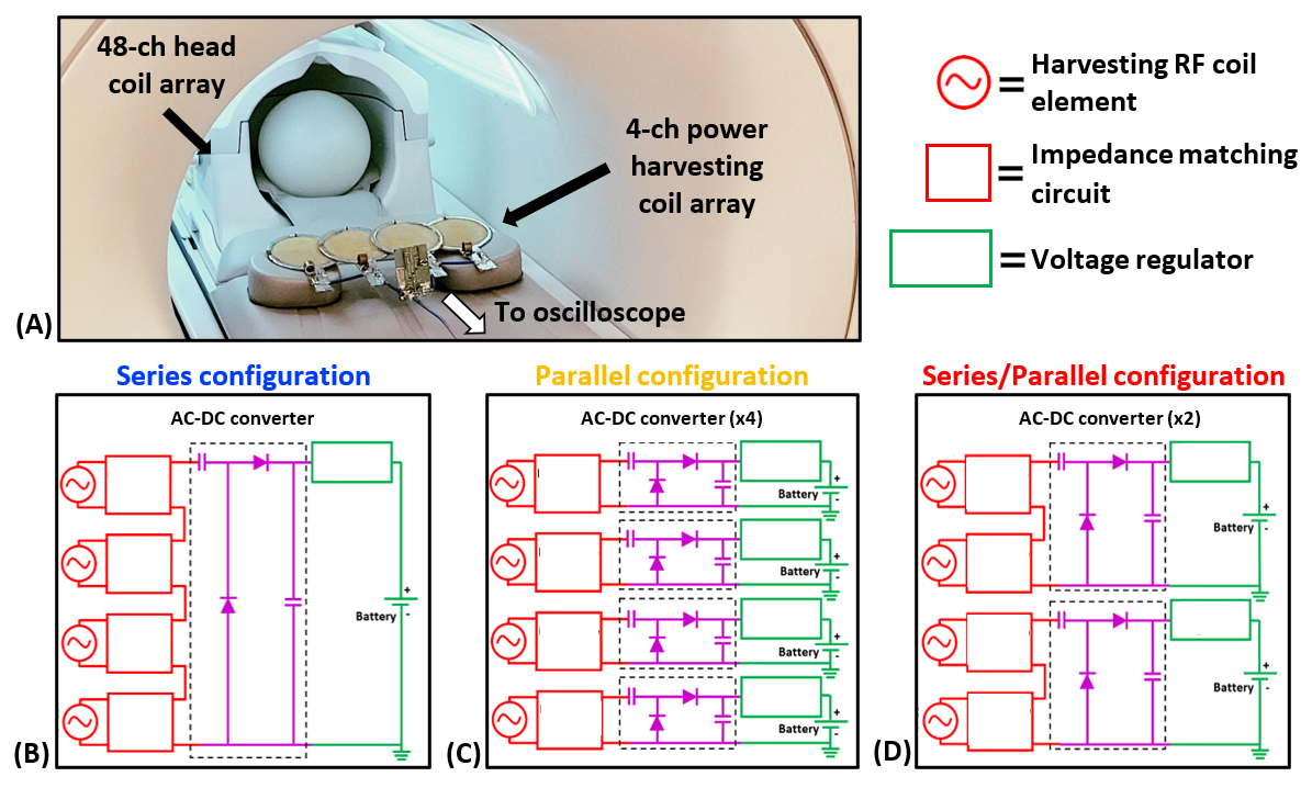
Figure 1: The harvesting coil array and electronics were placed in the scanner bore in a coronal plane maximize efficiency (A), with the coil outputs connected either in series (B), parallel (C), or a combination of series and parallel (D). The harvested RF energy (red) was first rectified using an AC-DC converter (purple) before being regulated and applied to the battery (green).
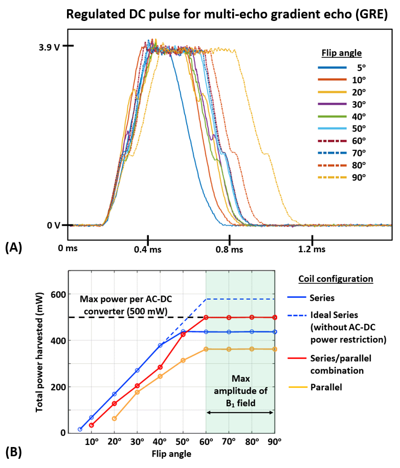
Figure 2: Unsmoothed DC pulses were applied to the battery for various flip angles during GRE image acquisition (A) with the power delivered to the battery calculated for each coil configuration (B).
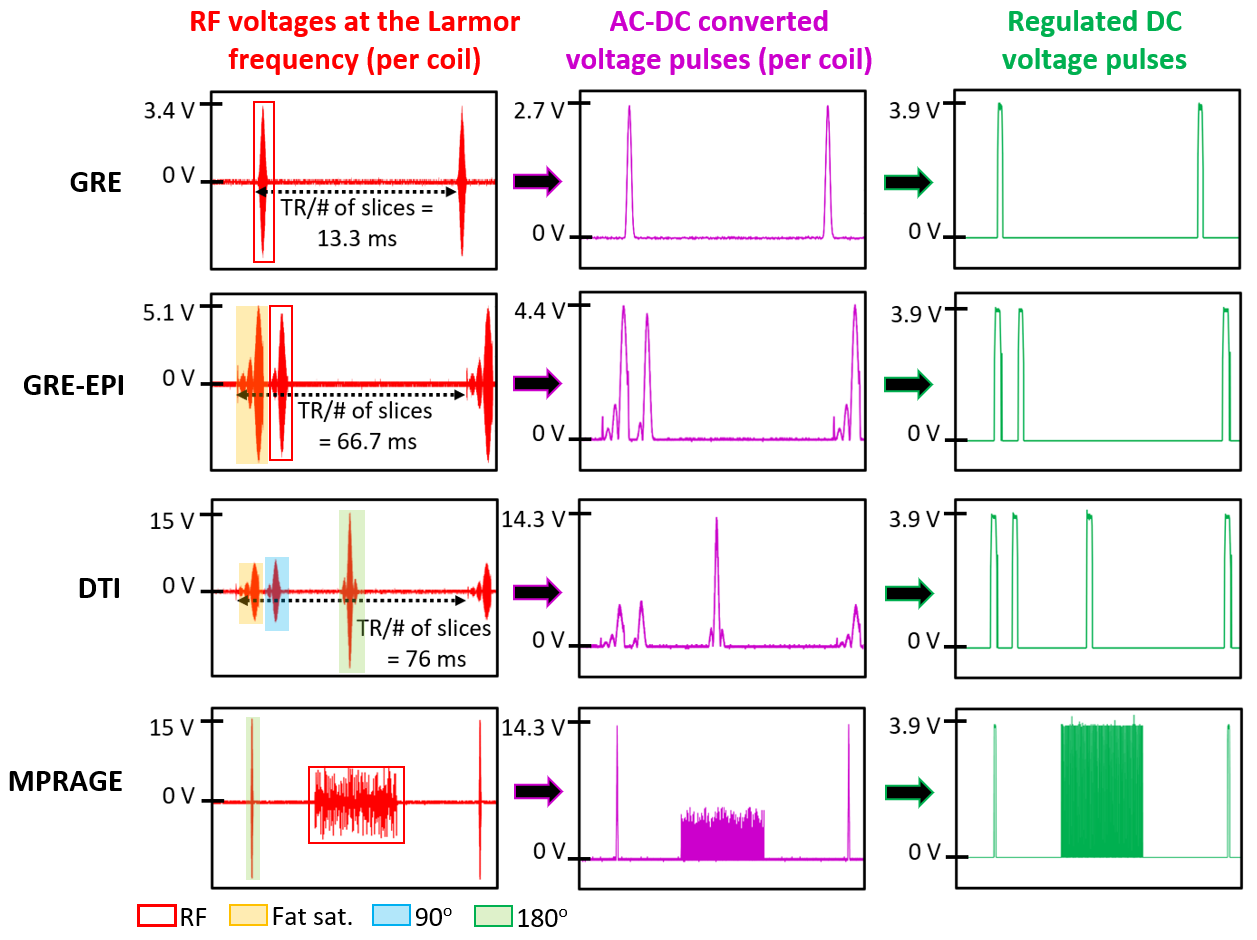
Figure 3: RF energy (red) was harvested during GRE, GRE-EPI, DTI, and MPRAGE image acquisitions and rectified (purple) using an AC-DC converter before being regulated (green) and applied to the battery.
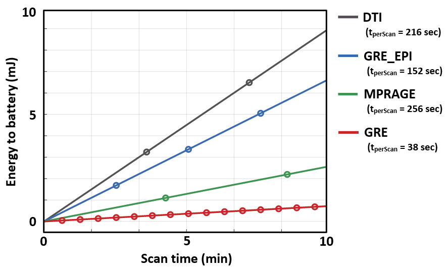
Figure 4: Energy applied to the battery over a duration of 10 minutes during GRE, GRE-EPI, DTI, and MPRAGE image acquisitions.