2001
Design of a Miniaturized High Impedance Preamplifier for 7T MRI1CEA Saclay/DRF/JOLIOT/NEUROSPIN/BAOBAB/METRIC, Gif-sur-Yvette, France, 2Multiwave Imaging SAS, Marseille, France, 3CEA Saclay/DRF/IRFU/DACM//LISAH, Gif-sur-Yvette, France
Synopsis
Coil arrays enhance human body performance for an MRI measurement both in speed and signal-to-noise ratio. However, size and cabling of such arrays can deteriorate the performance of the imaging, or put at risk the safety of the patient. A miniaturized preamplifier is proposed (dimensions 24mm x 11mm), to be placed directly onto the receive coil. The design needs to preserve a good performance (noise figure ≤ 1dB, gain ≈ 28dB), and provide high impedance to minimize the coupling to nearby coils.
Purpose:
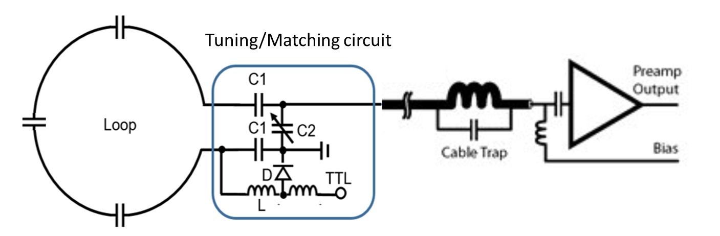
Traditional low-impedance preamplifier such as Wantcom preamplifier [1] use a tuning and matching circuit to match the coil impedance to 50 Ω as seen by the preamplifier and provide high-impedance as seen by the coil. This tuning and matching circuit is connected to the preamplifier by a l/2 cable length with a cable trap as shown in figure 1. The size and cabling of such arrays can deteriorate the performance of the imaging, thus we propose a high-impedance preamplifier that is connected directly to the coil without the need of the l/2 cable, another main advantage of our proposed preamplifier is the ease of matching and tuning it without the need to disconnect the preamplifier from the Matching/tuning circuit each time.Methods:
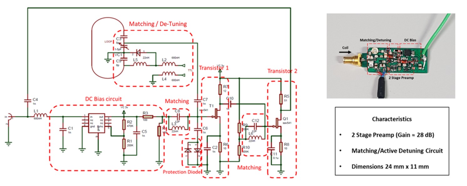
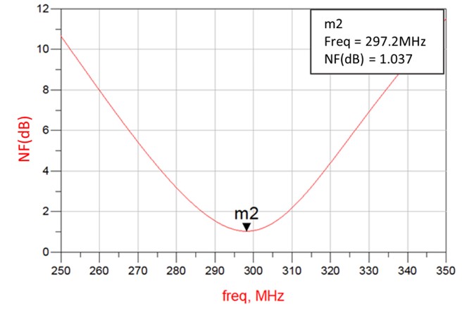
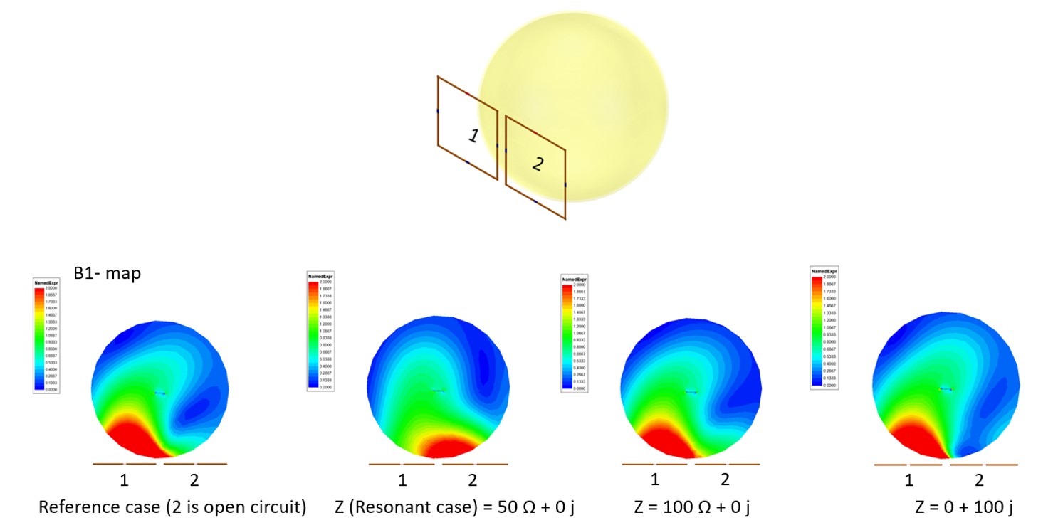
The circuit of the designed high impedance preamplifier is shown in figure 2. It is a two-stage preamplifier. The DC bias operating point is chosen from datasheet to exhibit stable thermal performance and minimum noise figure. A matching circuit is used, consisting of a band-pass filter (C8, L3 and C12, L6) that provides high impedance seen from the loop side for preamplifier decoupling, and an impedance close to the Zopt (optimal impedance needed to have a minimum noise figure) seen by the transistor input port [2-4]. A matching and a tunable capacitor is used to match the frequency of the coil to Larmor frequency. A diode and inductor are used for active detuning, a protection at input of the transistor is added using 2 shunt Schottky diodes to protect the transistor from high RF power. The stability of the preamplifier is achieved by adding a shunt resistor (R7, R5) at the output of the transistor. The stability and Noise Figure analysis was simulated using EM/Circuit Co-Simulation in Advance Design System ADS and it showed an unconditionally stable performance with Noise Figure of 1.04dB at 7T / 298 MHz (figure 3). Moreover, an HFSS simulation was carried out for preamplifer decoupling using two loops of diameter 7 cm separated by 1cm from each other, with a spherical phantom (σ = 0.78, ε = 72, diameter = 15 cm) as seen in figure 4. The aim is to find the required impedance Zblock at the coil output to obtain good decoupling between neighboring loops, and to observe the effect of the resistive and reactive parts of that impedance on decoupling performance. We have set one loop as a transmitter loop (tuned and matched to 50 W), and we have changed the impedance of the second loop to simulate the impedance that is provided by the preamplifier. We compare B1– maps with the open circuit reference case in situations where Zblock of the second loop is of a a low inpedance of 50 Ω , a pure resistance (100Ω + 0 j), and finally a pure reactance ( 0 + 100 jΩ).Results:
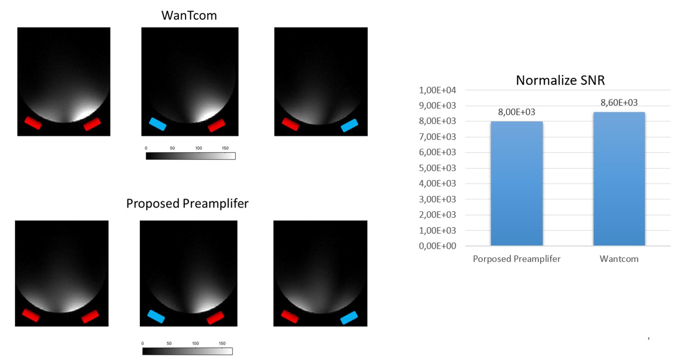
We can observe a change in the B1– map for second case which indicate a bad decoupling between loops,while we can notice a slight change in the B1– map in both second and third cases, which indicate that we have a good preamplifier decoupling, thus for a good preamplifier decoupling we must have an impedance of magnitude greater than 100Ω. Furthermore, simulation showed that the impedance provided by our preamplifier is of 10 – j150Ω which is good enough for our two loops preamplifier decoupling. In addition, a test was carried out in the MRI using 2-channel receive-only coils with a tunable loop as a transmit coil, and a spherical phantom as in our HFSS simulation in order to compare SNR performance and to verify the preamplifier decoupling response. It was noticed that the SNR values (Normalized to the flip angle) with the WanTcom preamplifiers and our proposed preamplifiers are close to each-other with a difference of less than 10% (Fig. 5, the red rectangles represent the loop position). Also, fig. 5 shows the preamplifier decoupling performance as seen by each channel (we used MATLAB to reconstruct the image of each channel by using Sum-of-Square), it can be noticed that both preamplifiers provide a good preamplifier decoupling performance.Conclusion:
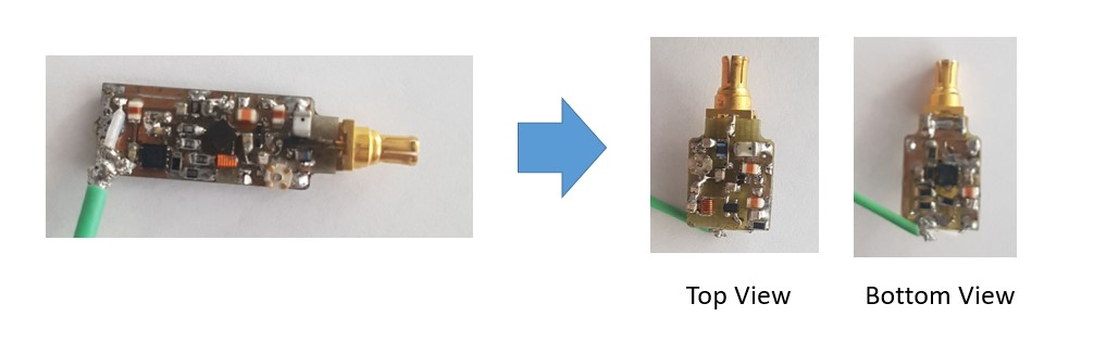
We proposed a miniturazied compact preamplifier design for 7T imaging, our main objective was to eliminate the use of cable between the matching circuit and the preamplifier and to ease the Matching/tuning method between preamplifier and the loop with the need to disconnect them. The preamplifier showed a good performance in both SNR and preamplifier decoupling compared to WanTcom preamplifier with a difference of less than 10%, this difference can be reduced by re-optimization of our preamplifier. In addition we have studied the preamplifier decoupling between two closely separated loops, and we have noticed that we need an impedance of magnitude greater than 100, but it is worse mentioning that having more loops (32 loops for example) need a higher impedance around 400 in order to provide a prefect decoupling between loops. Finally, the preamplifier can be more miniaturized by using Multilayer technology [5] as what we have done for our first stage preamplifier figure 6.Acknowledgements
These research activities have received funding from the European Union's Horizon 2020 research and innovation programme under grantagreement No 952106 (M-ONE project).References
1) http://www.wantcominc.com/DataSheets/WMA/WMA7RA-R5.pdf
2) Roemer, P.B., Edelstein, W.A., Hayes, C.E., Souza, S.P. and Mueller, O.M. (1990), The NMR phased array. Magn Reson Med, 16: 192-225
3) Fujita H, Zheng T, Yang X, Finnerty MJ, Handa S. RF surface receive array coils: the art of an LC circuit. J Magn Reson Imaging. 2013 Jul;38(1):12-25
4) ReykowskiA, Wright SM, Porter JR. Design of matching networks for low noisepreamplifiers. Magnetic resonance in medicine. 1995 Jun;33(6):848- 52.
5) G. Duchamp, S. Gauffre, L. Casadebaig And J. Pistre, a broadband microwave amplifier using multilayer technology
Figures