1999
Automated tuning of gate driver circuit using eGaN FETs
Natalia Gudino1
1LFMI, NIH, Bethesda, MD, United States
1LFMI, NIH, Bethesda, MD, United States
Synopsis
An automated tuning of the dual resonance LC network that forms the gate driver circuitry of a dual tuned RFPA is presented. Through this automated tuning the RFPA could be adapted from the control to operate at the selected 1H and X-nucleus frequencies.
Introduction
A dual-tuned optically controlled on-coil switch-mode RF power amplifier (RFPA) was presented to simplify the implementation of multi-nuclear multi-channel Tx hardware1. The optically controlled on-coil technology allows elimination of multiple coaxial connections, cable traps and matching networks required at each X-nucleus frequency. In this work an automated tuning of the dual resonance LC network that forms the gate driver circuitry of the RFPA is presented. This tuning is possible by a voltage-modulated effective inductor formed by the series of the voltage-modulated output capacitance of an eGaN FET and a fixed inductor2. Through this automated tuning the RFPA can be adapted from the control to operate at the selected 1H and X-nucleus frequencies.Methods
The dual-tuned on-coil RFPA can operate at different X-nuclei frequencies by the adjustment of a single inductor located in each of the dual resonance LC networks that drive the FETs. A variable effective inductor is formed by connecting the voltage-modulated output port capacitance of an eGaN FET device in series with a discrete inductor (Figure 1). The eGaN FET device and inductor value were selected to excite the Larmor frequencies of nuclei such as 13C, 23Na and 31P at 7T (70 MHz -150 MHz). The value of the effective inductor was controlled through the eGaN FET drain-source voltage which was automatically controlled by changing the duration of a pulsed version of the 10 MHz clock signal accessible in most commercial MRI scanners. This signal is optically received, amplified, and rectified on the RF amplifier board. The amplitude of the rectified voltage (drain-source voltage of the eGaN FET device) is a function of the duration of the pulsed 10 MHz carrier. A reset switch will set this voltage back to 0 V before the next MRI repetition time (TR). A simplified diagram of the dual-tuned RFPA highlighting the automated tuning circuitry and one LC dual resonance is shown in Figure 1. A model of the dual-tuned amplifier with the automated tunning circuitry was simulated in ADS Software (Keysight, Santa Rosa, CA). A stand-alone automated variable capacitor based on the proposed method was designed, simulated, and implemented to tune a small loop coil (Figure 2). The automated tuning was tracked by measuring the reflection coefficient (S11) of a probe coupled to the loop coil and connected to a network analyzer.Results
In this design, the optically controlled rectified voltage is 40 V, enough to enable the whole range of port capacitance values of the selected eGaN FET device. The simulated voltage and phase frequency response of the gate driver circuit of the dual-tune RFPA is shown in Figure 3. The values of the effective inductor that results from modulation of the eGaN FET port capacitance allowed switching of the FETs in push-pull configuration for the selected proton frequency (7T) and multiple lower frequencies (X-nuclei) in a ~50 MHz span. The automated tuning of the loop coil by the stand-alone optically controlled eGaN FET port capacitance is shown in Figure 4. Three repetitions were performed at each duty cycle value of the tune control signal. Through this method a 44 % maximum change in capacitor value was achieved with a single eGaN FET device.Discussion
An adaptable on-coil RFPA design to operate at most common MRI frequencies (60 MHz-300 MHz) was simulated. This hardware will allow excitation of different X-nuclei by automated tuning of the gate driver circuit and without hardware modifications. In addition, same amplifier could be used for 1H MRI in different scanner systems. The implementation of on-coil current sensing and monitoring as previously presented3,4 together with the optical automated control of the effective inductor of the LC network will make possible the implementation of self-tuning gate driver circuitry. This flexibility is possible with minimal modification of connections of the on-coil Tx chain and simple to implement with signals accessible on commercial MRI systems. Miniaturization of the optically controlled tuning circuit may be attractive for automatic tuning and matching5-8 of other hardware.Acknowledgements
No acknowledgement found.References
- Gudino N, et al. Proc. Intl. Soc. Mag. Reson. Med 2019. (Abstract 0765)
- Gudino N. International Patent Application PCT/US2021/040117 July 2021.
- Gudino N. et al. Magn Reson Med 2020;84:3494-3501.
- Gudino et al. Magn Reson Med 2018;79(5)2833-2841
- Katsikatsos G, Pruessmann KP. In: Proc. Intl. Soc. Mag. Reson. Med, 2012. (Abstract 2637)
- Sohn S-M et al. IEEE. Trans Biomed Circuits Syst. 2015;9:725-732.
- Keith GA et al. Magn Reson Med. 2015;73:2390-2397
- Muftuler et al. Journal of Magnetic Resonance 155,39–44 (2002)
Figures
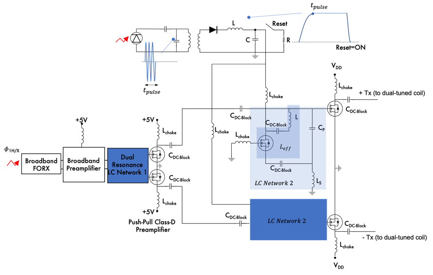
Figure 1: Simplified diagram of adaptable dual-tuned RFPA showing one of the four LC networks with optically controlled tunable effective inductance.
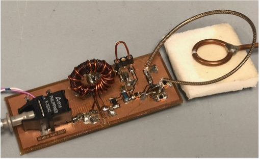
Figure 2: Photograph of prototype with stand-alone optically controlled eGaN FET capacitance resonating coaxial loop
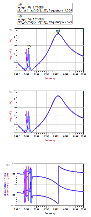
Figure 3: Simulated voltages (top) and phase (bottom) of tunable gate driver circuit
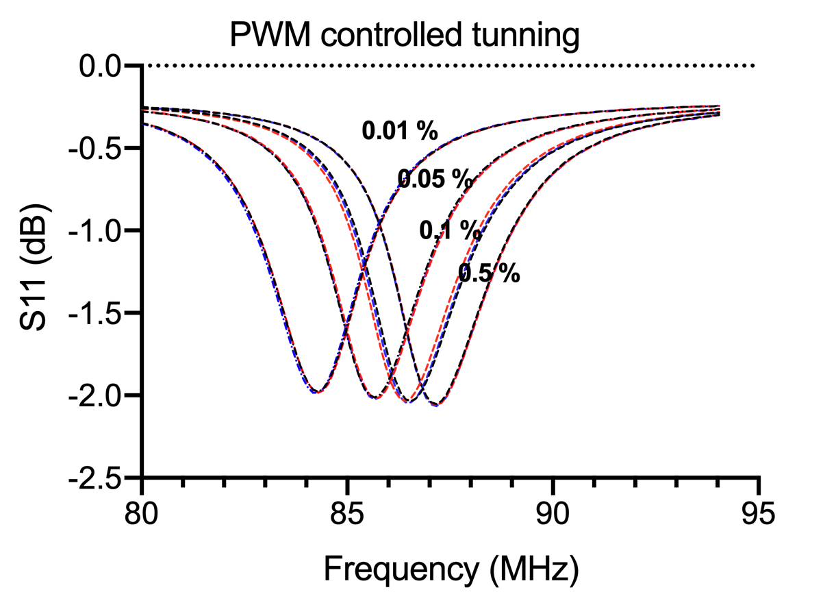
Figure 4: S11 measurement (3 repetitions) with an RF probe coupled to loop (not 50 Ω matched) resonated by a single eGaN FET device controlled by a pulsed optical 10 MHz signal.
DOI: https://doi.org/10.58530/2022/1999