1989
3D Bioprinted MRI-Trackable Regenerative Scaffold for Post-Implantation Monitoring1Institute of Biomedical Engineering, University of Toronto, Toronto, ON, Canada, 2Translational Biology & Engineering Program, Ted Rogers Centre for Heart Research, Toronto, ON, Canada, 3The Edward S. Rogers Sr. Department of Electrical and Computer Engineering, University of Toronto, Toronto, ON, Canada
Synopsis
3D bioprinted scaffolds are one of the most novel and promising tissue regenerative therapeutics currently in development (e.g. to repair damaged cardiac tissue). Validation of correct scaffold placement and retention post-implantation is essential, but it is challenging to visualize scaffolds in-vivo given their similar material properties to native tissue. In this study, a T1-reducing contrast agent, MnPNH2, was utilized to create an MR-trackable, bioprinted scaffold. In-vitro and in-vivo results confirmed the novel scaffold provided an environment conducive to cell growth and offered significant bright contrast for post-implantation scaffold monitoring in rats.
Introduction
Novel heart patches embedded with stem cells and cardiac cells represent one of the most promising regenerative paradigms to treat cardiovascular disease, and are intended to replace the need for heart transplantation, which has a mortality rate of 50% within 12 years1–3. Despite its promise, there remain many challenges toward its optimization and ultimate clinical translation, amongst which the immediate, non-invasive in-vivo confirmation of correct patch placement and retention is critical. We hypothesize that the use of a gadolinium-free, manganese-based T1 contrast agent4 can be used to label a 3D bioprinted scaffold and track its proper placement in-vivo post-implantation.Methods
Our bioink was composed of 7.5% gelatin, 1% alginate and tested for cell compatibility by integrating human embryonic kidney cells (HEK293T) at a density of 1 million cells/mL. A holding time of 15 minutes was set to allow the bioink to solidify before initiating printing. The bioink was printed onto the bioprinter bed as stacked sheets to construct a thick cardiac tissue scaffold (Figure 1). Printing was done at room temperature with a 25G tapered needle; printing speed/pressure were set to 6mm/s and 12-15psi, respectively. The final construct was immersed in a 100mM CaCl2 solution for 3 minutes to allow cross-linking, washed with PBS, immersed in cell media, and maintained in an incubator set at 37 , 5% CO2. Twenty-four hours before MRI, the scaffold was immersed in cell media/PBS +/+ labeled with 0.5mM MnPNH2 at room temperature. Cytotoxicity effects from this agent are negligible, and extensive in-vitro and in-vivo characterizations were previously completed on HEK cells under various labeling conditions5. Live/dead assay was used to test cell viability by labeling the cell/bioink mixture with 1µm calcein AM and 2µM Ethidium homodimer-1 to visualize living and dead cells, respectively. For our in-vivo studies, scaffolds were prepared in advance and implanted subcutaneously in Sprague Dawley rats in the lower dorsum. Tissue glue was used to secure scaffolds to muscle. Each rat was implanted with one labeled scaffold and one control scaffold on either side of its vertebrae. Rats were imaged in a prone position on a 7.0T scanner (BioSpec 70/30, Bruker, Ettlingen, Germany) using a B-GA12 gradient coil insert and a receive-only rat brain coil. T1 mapping was performed using turbo spin echo with multiple TRs: TR = [2500, 2000, 1500, 1000, 750, 500, 250] ms, TE = 9.5 ms, 1 average, echo train length = 2, 1.0 mm slices, and 0.2 x 0.2 mm in-plane resolution. In-vitro T1 mapping was performed using turbo spin echo with multiple TRs: TR = [4000, 2500, 1500, 1000, 750, 500, 250, 125, 50] ms, TE = 8 ms, 0.5 mm slices, and 0.2 x 0.2 mm in-plane resolution. High-resolution T1-weighted spin echo was also acquired at an in-plane resolution of 0.125 x 0.125 mm.Results
The bioprinted scaffold was designed to enhance cell survival and delivery: bioink fibres were printed at 200µm in diameter to permit cell-to-cell interaction and diffusion of oxygen/nutrients (Figure 1). Live/dead staining conducted 24 hours after bioprinting/labeling the scaffolds and repeated at 1, 2, and 3 weeks post-printing/labeling confirmed high cell viability and proliferation, with minimal cell death (Figure 2). In-vitro MRI of control and labeled scaffolds (0.5mM MnPNH2) using T1-weighted spin echo imaging and T1 mapping revealed the intricate architecture of the bioprinted geometry (Figure 3). In-vivo rat MRI results are shown in Figure 4. Qualitatively, we could easily identify and locate the labeled scaffold, whereas the control scaffold was not distinguished from surrounding skin and muscle. Measurement of T1 relaxation times confirmed that the T1 reductions observed in vitro were replicated in vivo (Table 1).Discussion
Our results demonstrate MnPNH2, a highly efficient T1 contrast agent that offers high sensitivity and specificity on MRI, confers a significant T1 reduction of the bioprinted scaffold without adverse effects on cell viability. In-vivo studies confirmed that labeled bioprinted scaffolds were readily identified post-implantation and could be tracked to detect potential scaffold migration. This in-vivo tracking capability will be immensely helpful in optimizing scaffold-based tissue regeneration applications.Conclusion
We report, to our knowledge, the first T1-weighted MR-detectable and cell-compatible bioprinted scaffold intended for tissue regeneration. This platform for in-vivo post-implantation monitoring can facilitate optimization of scaffold-based regenerative medicine and tissue engineering.Acknowledgements
S.L is funded by an Ontario Graduate Scholarship. This work is supported by a Natural Sciences & Engineering Research Council of Canada (NSERC) Discovery Grant, Dean’s Spark Professorship, and a Ted Rogers funded Seed Grant.
References
1. Izadifar, M., Chapman, D., Babyn, P., Chen, X. & Kelly, M. E. UV-Assisted 3D Bioprinting of Nanoreinforced Hybrid Cardiac Patch for Myocardial Tissue Engineering. Tissue Eng Part C Methods 24, 74–88 (2018).
2. Ong, C. S. et al. 3D bioprinting using stem cells. Pediatr. Res. 83, 223–231 (2018).
3. Alraies, M. C. & Eckman, P. Adult heart transplant: indications and outcomes. J Thorac Dis 6, 1120–1128 (2014).
4. Szulc, D. A. & Cheng, H.-L. M. One-Step Labeling of Collagen Hydrogels with Polydopamine and Manganese Porphyrin for Non-Invasive Scaffold Tracking on Magnetic Resonance Imaging. Macromolecular Bioscience 19, 1800330 (2019).
5. Venter, A. et al. A manganese porphyrin-based T1 contrast agent for cellular MR imaging of human embryonic stem cells. Sci Rep 8, 12129 (2018).
Figures
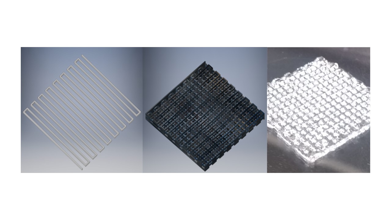
Figure 1. One layer of the cardiac scaffold, 20mm x 20mm x 0.2mm (left) designed in AutoCAD. Stacked sheets forming thick cardiac tissue construct, 20mm x 20mm x 0.8mm (middle) designed in AutoCAD. Final 3D bioprinted scaffold design after crosslinking (right).
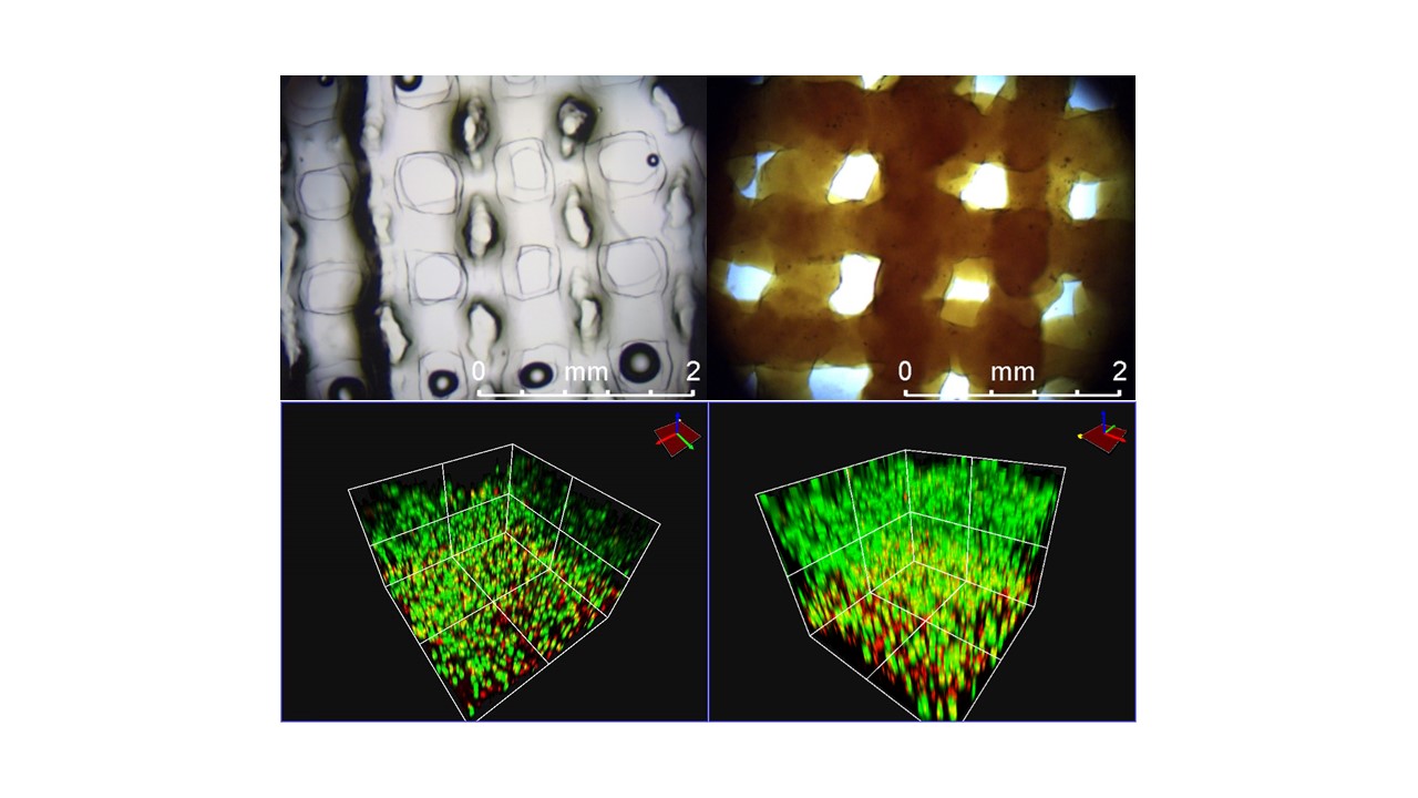
Figure 2. Bioprinted control scaffold immediately post-printing (top left) and bioprinted scaffold labeled with 0.5mM MnPNH2 for 24 hours (top right). Images captured at 5x magnification on bright-field imaging. 3D reconstruction from confocal microscopy of control (bottom left) and labeled (bottom right) scaffolds two weeks post printing/labeling with HEK293T cells, stained with a live/dead assay. Live cells appear green; dead cells appear red.
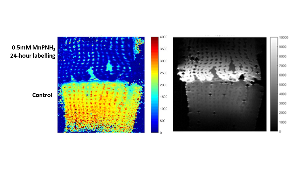
Figure 3. In-vitro T1 map in msec (left) and T1-weighted spin echo (right) of the bioprinted scaffolds labeled with MnPNH2 for 24 hours with 0hr retention (top scaffold) and control (bottom scaffold).
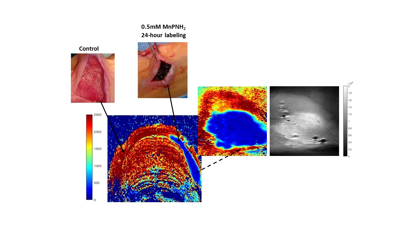
Figure 4. In-vivo T1 map (in msec) of a rat implanted with a bioprinted control (left side) and labeled (right side) scaffold, imaged immediately post-implantation. T1 map shown at the centre was obtained in the axial plane, whereas the zoomed in T1 map was captured with an oblique slice 1mm thick. T1-weighted spin echo of the labeled scaffold captured with an oblique slice is shown beside the T1 map. Photographs of implants are also shown.
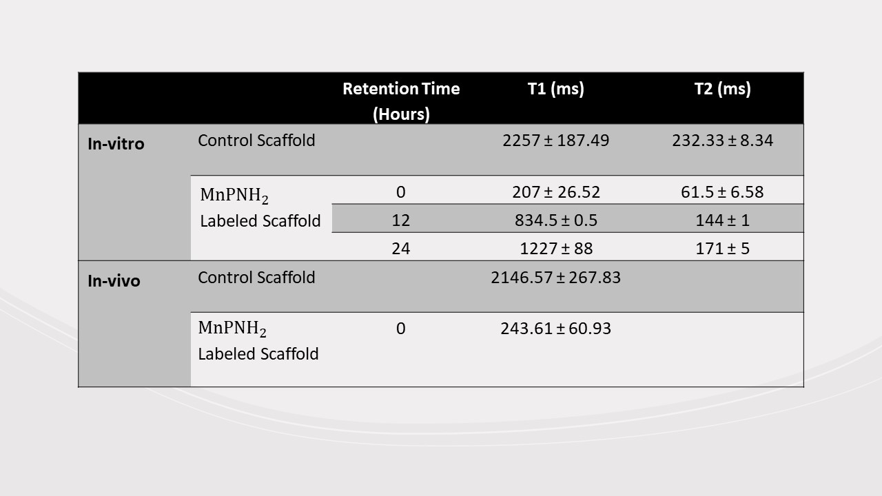
Table 1. In-vitro and in-vivo T1 and T2 relaxation times of control scaffold and MnPNH2-labeled scaffold with various retention times.