1950
Motion tracking verification with a 3D printed compliant mechanisms and laser interferometry
Christoph Michael Schildknecht1 and Klaas Paul Prüssmann1
1Institute for Biomedical Engineering, ETH Zurich and University of Zurich, Zürich, Switzerland
1Institute for Biomedical Engineering, ETH Zurich and University of Zurich, Zürich, Switzerland
Synopsis
Precisely characterizing motion tracking modalities in the MRI bore is quite a challenge. Especially when not only static positions ought to be evaluated, but also dynamic characterization is desired. In this work, we show how a compliant mechanism in the form of a folded-beam suspension can be utilized for accurate dynamic positioning. A piezoelectric actuator drives the system, and position feedback is acquired with a laser interferometer. Testing the system with short-wave motion tracking revealed a sub-micrometre agreement.
Introduction
Prospective motion correction schemes have demonstrated great value for human brain MRI1. The performance of such correction pivots around the fidelity of the utilized motion tracking modality. Therefore for the development and characterization of a motion tracking modality, it would be essential to have test capabilities suiting the sensing specification. However, complete characterization, including dynamic frequency responses, is hardly ever done. One main hindrance is that many motion tracking modalities require the MRI scanner in order to operate. Therefore a versatile motion tracking bench needs to be able to operate inside an MRI scanner, which is not easily done.In this work, we show how a 3D printed compliant mechanism combined with a laser interferometer one could achieve a high-performance motion actuation system for deeper motion tracking benchmarking.
Methods
In order to accurately move the test object in a controlled manner, the mechanical setup does not only needs to be stiff but must not have any play or backlash. Compliant mechanisms are ideally suited for such a purpose since they do not have any moving parts and joints, but instead, they are one structure that flexes in a controlled manner. The folded-beam suspension is very well suited for a linear motion stage, as it allows only movement in one direction and is very stiff in the other directions2.A folded-beam suspension setup was FEM simulated with COMSOL, and the results are shown in Fig. 1. In the simulation, nylon was assumed to be the material of choice, but later, during 3D printing, PLA was selected, which will lead to some scaling in the simulation results. The part was printed on a Prusa i3 mk3 FDM 3D printer and afterwards tested on a manual mill with a digital DRO and an optical scope, as shown in Fig. 2. The folded-beam suspension has a flexible lever as input reduction that is actuated with a screw onto which a large knob is mounted, allowing fine control over the input state.
Based on the same folded-beam suspension, a second version linear motion stage was 3D printed. In the second version, the actuation is done with a piezoelectric actuator, and for precise position feedback, a laser interferometer was included. Fig. 3 shows the setup, including a mounted short-wave marker3,4 for later testing. A “Blackmagic Pocket Cinema Camera 6k” was used as an optical detector where the interference pattern was shining directly onto the image sensor. The camera was operated with 120 frames per second. An example of a 1Hz oscillation is shown in Fig. 4.
As an initial validation experiment, a short-wave motion tracker was mounted on the folded-beam suspension and laser interferometer data was simultaneously acquired with the short-wave data while the piezo actuated the system.
Results
The FEM simulation resulted that when the input is actuated by 5mm, which is five times 360 degrees on the input, the output should move by 1.150mm in the desired direction and 0.0006mm and 0.000026mm in the other directions. Further, when 5N of force is vertically applied on the carrier, it should move by 1.6nm, 2.4um and -13um in x-, y-, z-direction.The 3D printed motion stage moved by 825um when inputting 10mm. The flexible lever input reduction was due to the higher young’s modulus of PLA by a factor of 2.8 more effective. Linearity regarding the input was inside a 2% tolerance band, as shown in Fig. 2.
The interferometer precision was measured to be 0.9nm at a bandwidth of 60Hz and was mainly limited by ambient vibrations and air movement.
Measuring the interferometer and the short-wave tracker simultaneously, as shown in Fig. 5, resulted in a close sub-micrometre agreement of both modalities.
Discussion and conclusion
The compliant mechanism folded-beam suspension reached the desired anisotropy in stiffness, allowing precise measurements along one axis. The linear stage was verified with the short-wave tracker to be accurate within expected margins. The current stage is not MR compatible, but with the exchange of a few screws, it could also be operated in the MRI bore. One might want to replace the camera with at least two photodiodes, thereby sampling the interference pattern sparse but almost arbitrary high speed and MR compatible.The system could be expanded to 3DOF, for example, based on the work the OpenFlexure project has conducted5. It is also conceivable that a complete 6DOF MRI-compatible motion stage with six laser interferometers could be built with a compliant mechanism hexapod and cubic mirrors.
Also, one interesting idea is that the presented motion stage could be used for precise diffusion experiments where the motion stage would move a gelled phantom during the diffusion encoding gradients.
Acknowledgements
No acknowledgement found.References
- Maclaren, J., Herbst, M., Speck, O. & Zaitsev, M. Prospective motion correction in brain imaging: A review. Magnetic Resonance in Medicine 69, 621-636, doi:10.1002/mrm.24314 (2013).
- Howell, L. L. in Encyclopedia of Nanotechnology (ed Bharat Bhushan) 457-463 (Springer Netherlands, 2012).
- Schildknecht, C. M., Brunner, D. O., Schmid, T. & Pruessmann, K. P. Design considerations for short-wave motion tracking. Proc. Intl. Soc. Mag. Reson. Med. 28 (2020).
- Schildknecht, C. M. et al. Wireless motion tracking with short-wave radiofrequency. Proc. Intl. Soc. Mag. Reson. Med. 27 (2019).
- Collins, J. T. et al. Robotic microscopy for everyone: the OpenFlexure microscope. Biomed. Opt. Express 11, 2447-2460, doi:10.1364/BOE.385729 (2020).
Figures
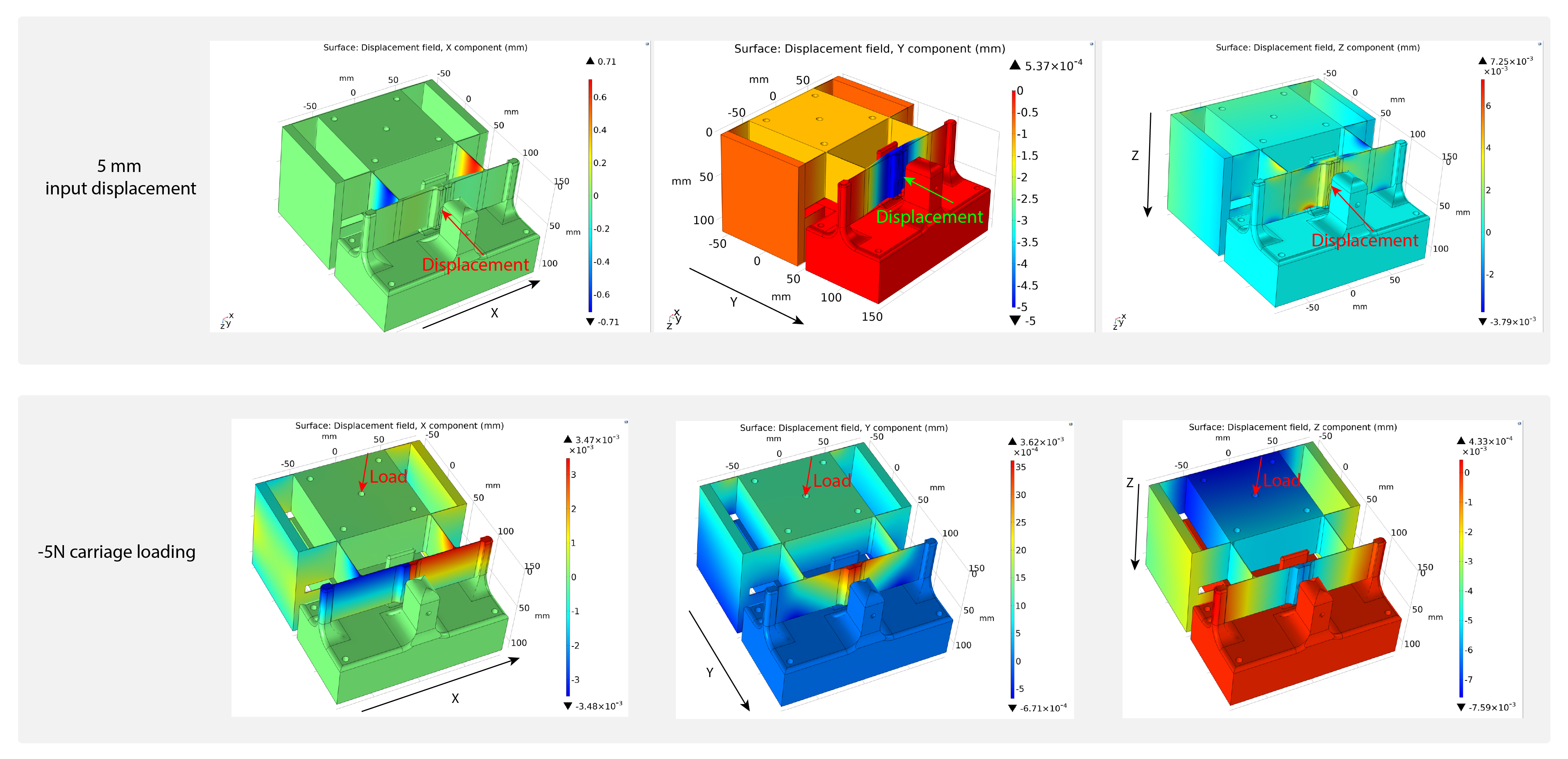
FEM
simulations of the folded-beam suspension are shown here. The top row displays
the surface displacement when the input is displaced by 5mm through the hole in
the front on the lever arms. The second row shows the surface displacement when
a vertical load is applied to the carrier, resembling the effect when weight is
put on the carrier. An example would be an MR phantom.
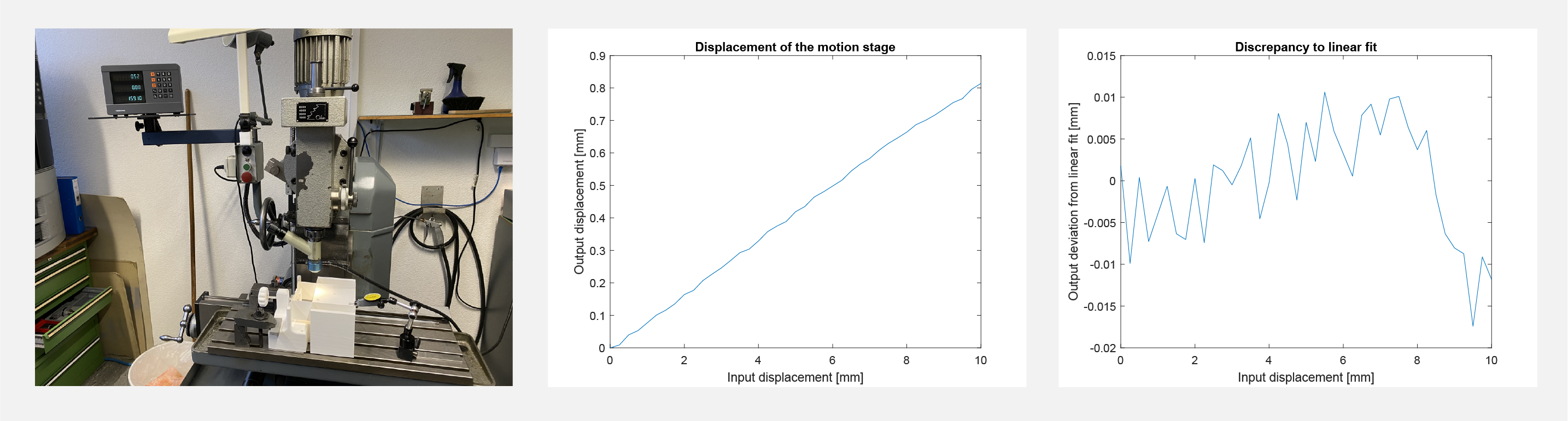
Shown here is the measurement of the
folded-beam suspension given input actuation over the rotary knob. As can be
seen, the device is very linear and deviates less than 2% from the linear relationship.
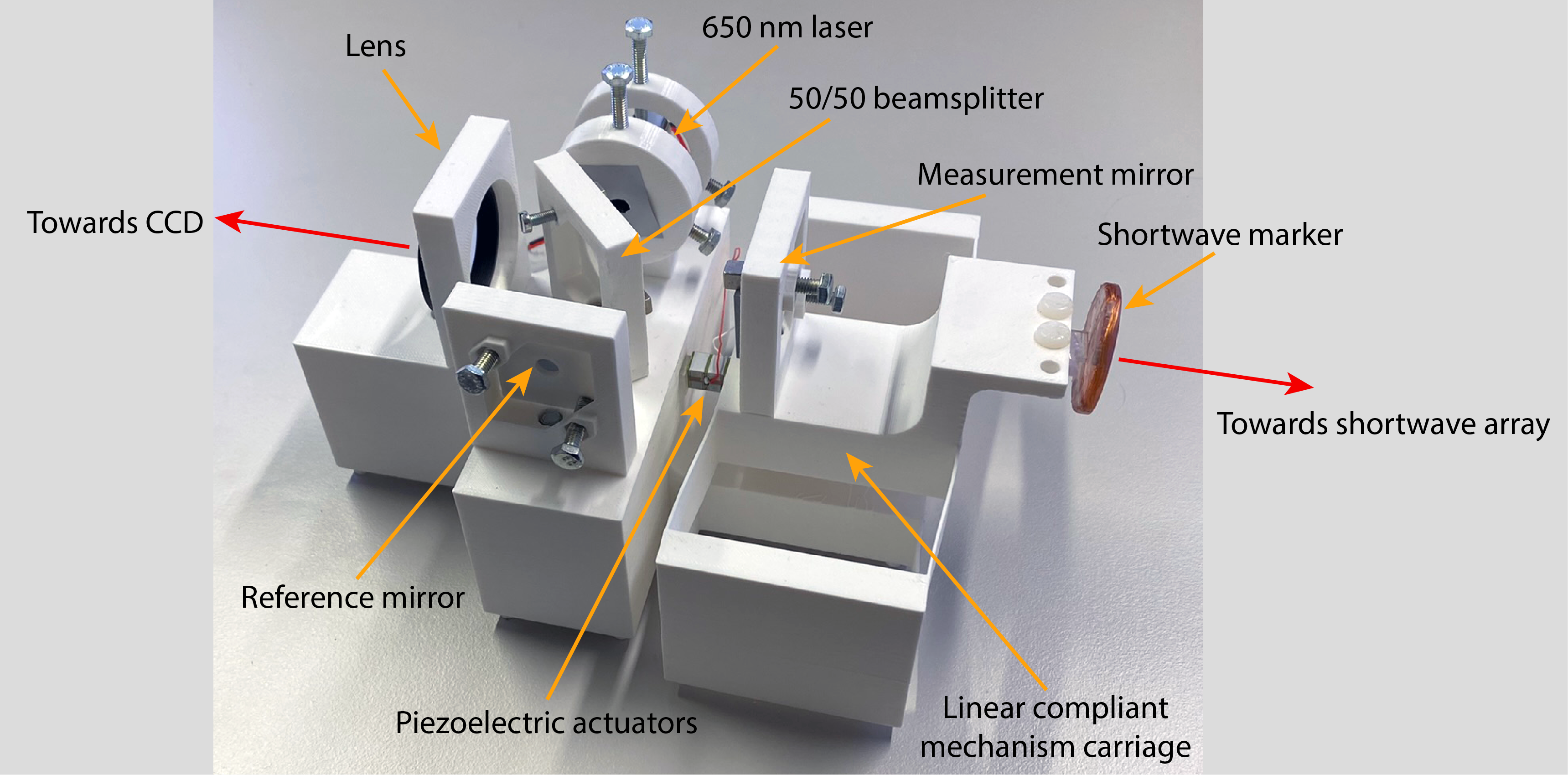
Shown here is the second version of the linear
motion stage. On the right side of the piezoelectric actuator is the compliant
mechanism folded-beam suspension. On the left side is the interferometer on the
structure that is fixed in place during a measurement.
Shown
is an animation of a sample interference pattern when the piezo is actuating
the motion stage with 1Hz a peak to peak amplitude of approximately 535nm.
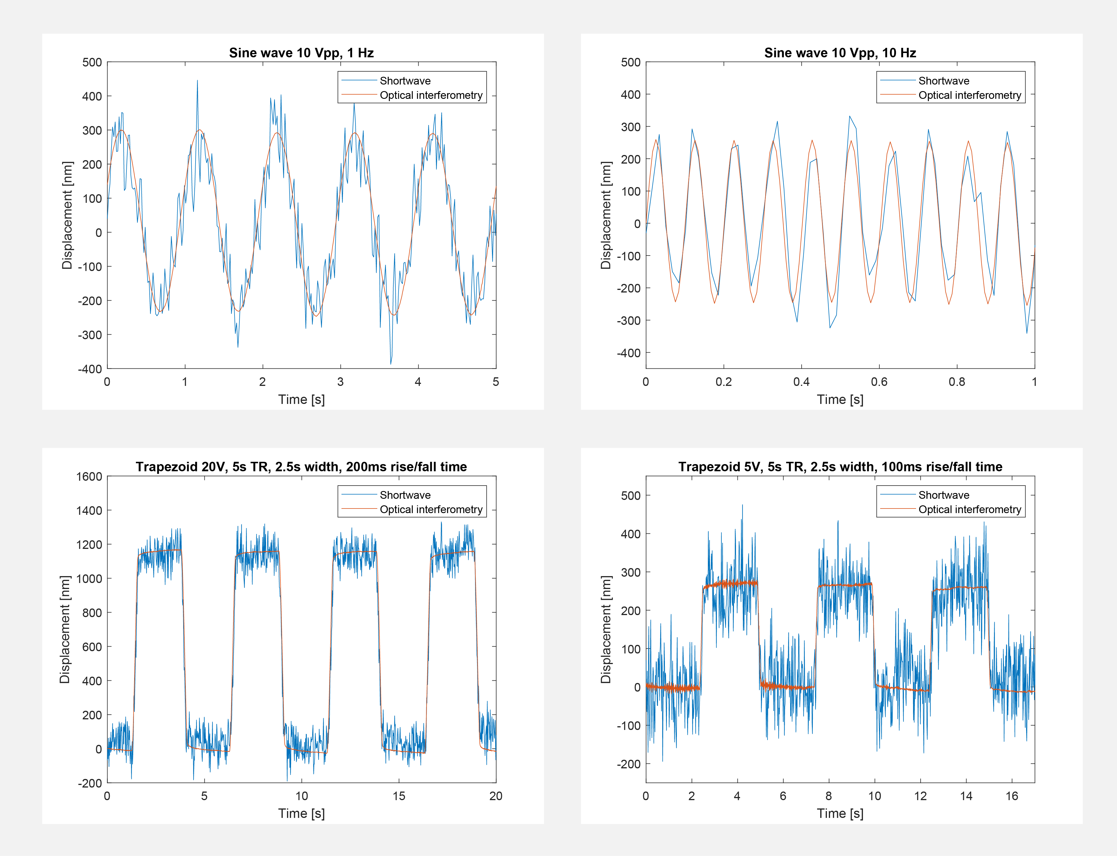
Shown
here are different measurements where sinusoidal voltages or trapezoidal
voltages actuated the piezo. As can be seen, there is close agreement between
both methods.
DOI: https://doi.org/10.58530/2022/1950