1903
Flexible six-channel knee array for MRI at 0.55T1Bernard and Irene Schwartz Center for Biomedical Imaging, Department of Radiology, New York University Grossman School of Medicine, New York, NY, United States, 2Center for Advanced Imaging Innovation and Research (CAI2R), Department of Radiology, New York University Grossman School of Medicine, New York, NY, United States, 3Siemens Medical Solutions USA Inc., Malvern, PA, United States, 4Siemens Healthcare GmbH, Erlangen, Germany
Synopsis
New-generation 0.55T systems require a suite of tailored coils to preserve image quality that is expected from higher field systems. We built a six-channel coil array for knee MRI using RG58 coaxial cable loops, which have adequate mechanical flexibility to wrap tightly around the leg and suitably low conductive loss at 23.55MHz. Initial findings show that the dedicated coil outperformed a general-purpose counterpart and suggest that clinical quality knee imaging is feasible.
Introduction
Amidst pursuit of faster scan time and better signal-to-noise ratio (SNR), low-field MRI systems (<1.5T) are often overlooked, especially in musculoskeletal applications such as knee imaging that require high spatial resolution. Wide-bore new-generation 0.55T systems, recently cleared by the FDA for clinical imaging, can offer distinct advantages such as improved affordability, accessibility, and patient comfort while preserving a diagnostic image quality. They also benefit from reduced susceptibility artifacts and specific absorption rates, which can be advantageous for patients with metal implants or hardware1,2.Since there is no dedicated knee coil array commercially available on such systems, we set out to design one. We based the design on coaxial cable loops whose flexibility allowed the array to be tightly wrapped around the knee. To find the best conductor amongst off-the-shelf options, we measured the quality factor (Q) of loops made from different coaxial cables and loop sizes. The final design was a six-channel array of RG58 cable loops that we compared against a makeshift reference array consisting of body and spine coils that were improvised for knee imaging.
Methods
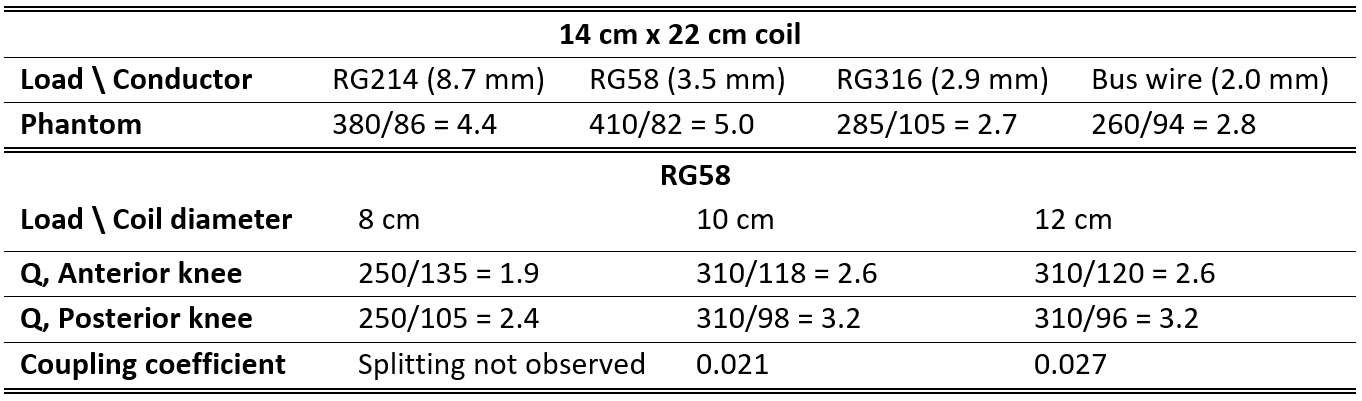
Our goal was to design a mechanically flexible array to maximize coil-tissue coupling. While several flexible conductor substrates have become available3-7, we chose to implement coaxial cable-based loops due to their widespread availability, low cost, robustness and ease of assembly8. To explore design options, we measured the Q-value of test loops (14cmx22cm) built using three off-the-shelf coaxial cables with a range of diameters (RG214, RG58, and RG316) along with a 12AWG copper bus wire that was considered a gold standard reference. The cables were made to resonate at 23.55MHz by inserting one capacitor in series with the outer shields. The inner conductors were not connected (electrically floating). Q-values were measured with the loops in free space and while loaded with a conductive phantom.The RG58 coaxial loop was found to have a Q-ratio of 5.0. Given the relatively high Q-ratio, we built smaller RG58 loops (∅=8,10,12cm) and measured Q-ratios and coupling coefficients $$$\left(\begin{array}{c}\frac{f_{1}-f_{2}}{ f_{0}}\\ \end{array}\right)$$$ when positioned anterior and posterior to a human knee, where f1 and f2 are the resonant frequencies of the two-coil system and f0 is the resonant frequency of a single coil.
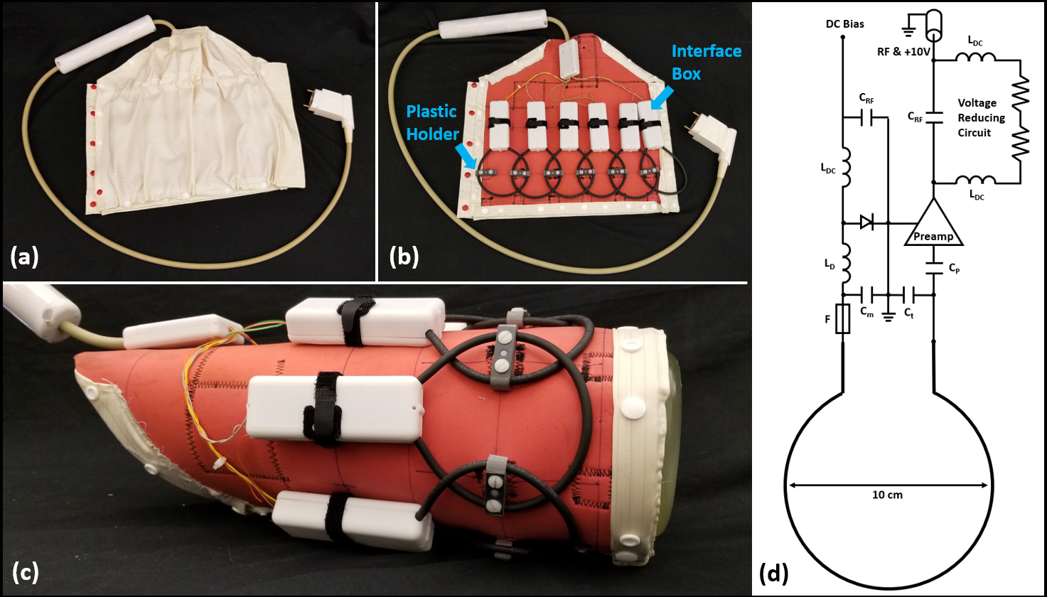
Considering both Q-ratio and coupling, we chose to construct a six-channel array out of 10 cm loops. The loops were arranged in one row that was wrapped around the knee. Adjacent loops were linked together by plastic hinges that allowed mechanical flexibility while maintaining geometric overlap for inductive decoupling. The loops were connected to a board that contained a preamplifier, protection fuse and components for matching, detuning, and preamplifier decoupling. The boards were enclosed in rigid plastic and the assembly in flame-resistant fabric (Figure 1).
The coil was evaluated on a commercial MRI system (1.5T MAGNETOM Aera; Siemens Healthcare, Erlangen, Germany) modified to operate as a prototype at 0.55T by comparing SNR in a phantom and image quality in clinically relevant sequences to those acquired with a reference coil. The reference coil was a six-channel body array in combination with an 18-channel spine array that originally were built for 1.5T and subsequently re-tuned to 23.55MHz. The reference coils were repurposed for knee imaging by wrapping the body array around the anterior knee and using the spine array to cover the posterior knee.
Results and Discussion
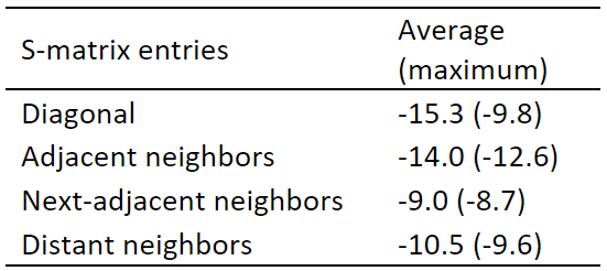
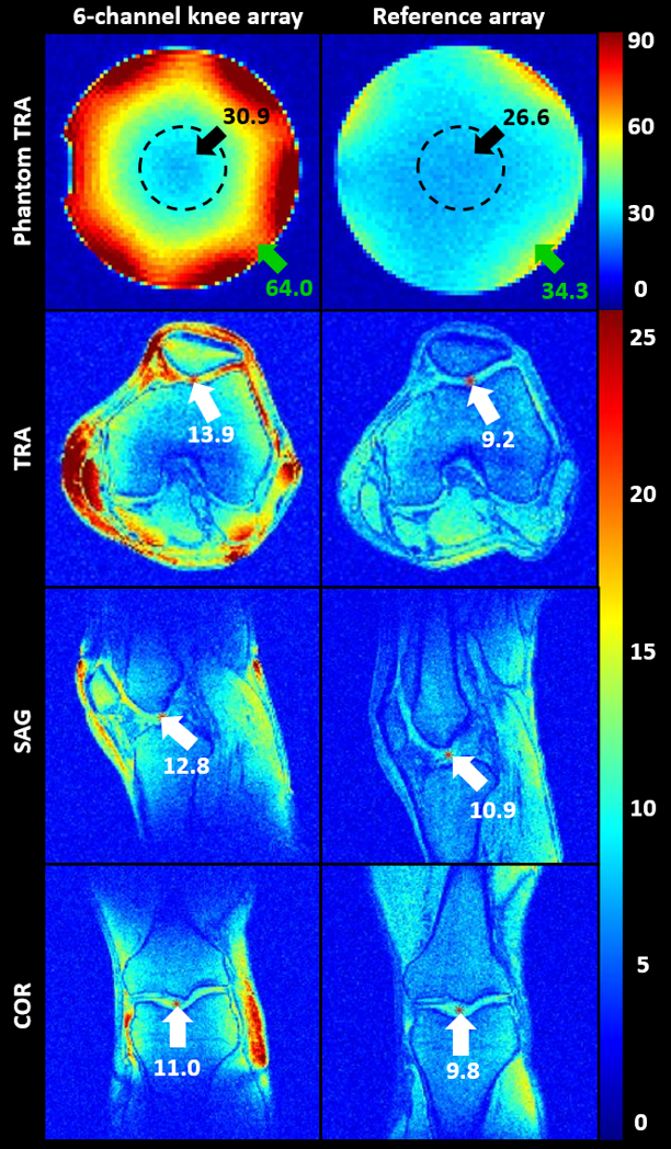
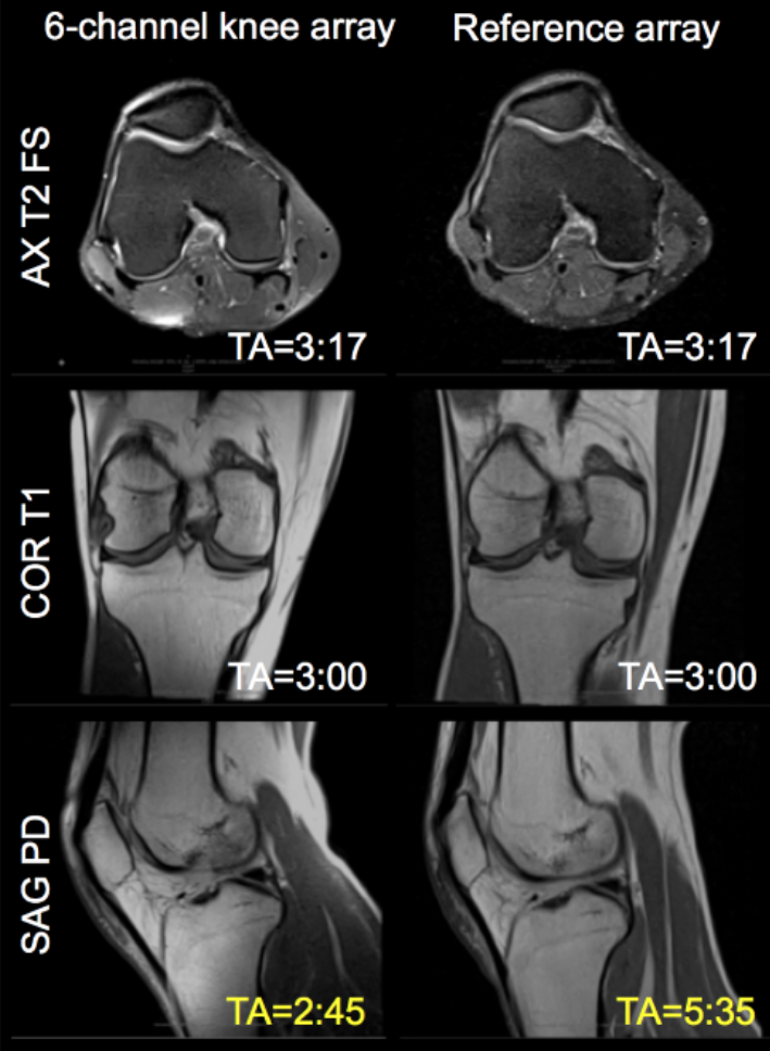
The RG58 coaxial cable loop Q-ratio was greater than other candidates, including that constructed using rigid bus wire (Figure 2, top panel). Using RG58, we found that loops with 12cm diameter had a reasonable Q-ratio of 3.2. However, the coupling coefficient between two 12cm loops placed anterior and posterior to a knee was 0.027, which could degrade SNR. In comparison, 10cm loops had similar Q-ratio but lower coupling (Figure 2, bottom panel).The scattering matrix measured on the six-channel array showed adequate decoupling (Figure 3). The SNR maps showed that the array provided approximately 16% advantage over the makeshift reference array in a 4 cm ROI in center of the phantom and 87% gain in voxels outside the ROI (Figure 4). This SNR advantage translated into improved image quality (Figure 5).
In conclusion, we designed and implemented a dedicated knee coil for 0.55T that outperformed a makeshift reference array. Although image quality was not rigorously evaluated, it appears that clinically acceptable knee examinations are feasible at low field with a dedicated coil. The coils were formed with off-the-shelf RG58 cable, which has slightly larger cross-sectional diameter than RG316 that was used by our group in an array with similar geometry operating at 123.2MHz8. As expected, RG58 is preferred to reduce conductor loss at 23.55MHz while maintaining sufficient flexibility to allow a tight fit to the anatomy, thus maximizing coil-tissue coupling. One limitation of the single-row array is that it does not cover “extended field-of-view exams” nor does it allow longitudinal parallel imaging acceleration. These limitations could in principle be overcome by replicating the existing array to form a two-row array. Such an array deserves exploration while keeping in mind that increased coil coupling may present a practical hurdle.
Acknowledgements
This work was partially supported by NIH grant R01 DK114428 and was performed under the rubric of the Center for Advanced Imaging Innovation and Research (CAI2R; www.cai2r.net) at the New York University School of Medicine, which is an NIBIB Biomedical Technology Resource Center (NIH P41 EB017183).
The authors would like to acknowledge the assistance of Siemens Healthcare in the modification of the MRI system for operation at 0.55T under an existing research agreement between NYU and Siemens Healthcare.
References
1. Marques, J.P., Simonis, F.F. and Webb, A.G. (2019), Low-field MRI: An MR physics perspective. J. Magn. Reson. Imaging, 49: 1528-1542.
2. AE Campbell-Washburn, R Ramasawmy, MC Restivo, I Bhattacharya. Opportunities in interventional and diagnostic imaging by using high-performance low-field-strength MRI. Radiology 293 (2), 384-393.
3. Port A, Luechinger R, Albisetti L, et al. Detector clothes for MRI: A wearable array receiver based on liquid metal in elastic tubes. Sci Rep. 2020;10(1):8844.
4. Port A, Luechinger R, Brunner DO, Pruessmann KP. Elastomer coils for wearable MR detection. Magn Reson Med. 2021;85(5):2882-2891.
5. Corea JR, Flynn AM, Lechene B, et al. Screen-printed flexible MRI receive coils. Nat Commun. 2016;7:10839.
6. Vincent JM, Rispoli JV. Conductive thread-based stretchable and flexible radiofrequency coils for magnetic resonance imaging. IEEE Trans Biomed Eng. 2019;67(8):2187-2193.
7. Zhang B, Sodickson DK, Cloos MA. A high-impedance detector-array glove for magnetic resonance imaging of the hand. Nature Biomedical Engineering 2018;2(8):570-577.
8. Siddiq SS, Lakshmanan K, Walczyk J, Bruno M, Brown R. Wearable Coil for Knee Flexion MRI. International Conference on Electromagnetics in Advanced Applications. 2021. p 378.
Figures