1900
A flexible, 4-channel head array for 0.2T readout FCI (Field-Cycling Imaging).1Medical Physics, University of Aberdeen, Aberdeen, United Kingdom, 2GE Healthcare, Waukesha, WI, United States
Synopsis
A 4-Channel Head Coil RX Array has been created supporting Field-Cycling Imaging studies at an 8.5 MHz readout frequency. Head imaging to date, has been accomplished with a quadrature TX/RX birdcage coil.
The array goals include improved SNR, enhanced patient comfort, peripheral compatibility, with fast application to various sized heads.
Evaluation with healthy volunteers is now underway. The array appears well tolerated by individuals when compared to the 8-rung birdcage, accommodating a communication headset, and leaving the face quite open.
SNR is comparable to the birdcage at the image center and improved as you move towards the array elements.
Introduction
Volunteer experiments with a Field-Cycling Imaging (FCI-MRI) scanner are underway, studying relaxation behaviors of various healthy and diseased tissues1 . This technology derives from MRI and, generally, reception is done at or near 0.2 T (protons resonating near 8.5MHz). Head studies have utilized a rigid quadrature TX/RX birdcage with careful tuning per volunteer to optimize the performance, but this is impractical and required careful procedures that were lengthy and prone to error.A 4-channel, close-fitting flexible head array has now been developed targeting improved SNR, enhanced patient comfort, peripheral compatibility, with fast application to various sized heads. The coil consists of 4 square 17.5 cm elements packaged in closed cell neoprene foam and interfaced to low impedance preamplifiers. The elements overlaps adjust for smaller or larger head compatibility.
Methods
Anthropometric data2 indicates a coil accommodating a 60 cm head would cover the majority of large volunteers, and a coil accommodating 55 cm would work for the majority of smaller volunteers. Four 17.5 cm sided square loops, formed onto a 62 cm cylinder (2 cm to account for about 1 cm thick packaging), resulted in 2cm overlaps. The overlaps are increased to 3.25 cm to form onto a 57 cm (2 cm to account for about 1 cm thick padding) cylinder. The element length was chosen for good brain to brain stem coverage and to try and keep the face element open below the mouth.Based on earlier positive work with multi-turn litz wire3, the loops were implemented at two turns utilizing HF -Litz 1600 strand x 0.020mm Elektrisola Co., Reichshof-Eckenhagen, Germany. Because of the flexible, adaptable nature of the coil and its’ variable overlaps, preamplifier decoupling was essential for the design4. Enhanced preamplifier decoupling was achieved by utilizing a high matching impedance transformation with a low input impedance amplifier optimized for a >150-ohm source (WMA-08HB WanTcom Inc., Chanhassen, MN, USA). The preamplifier, matching, and protection circuitry were packaged and located 8 cm from the loops, superior to the head.
Results
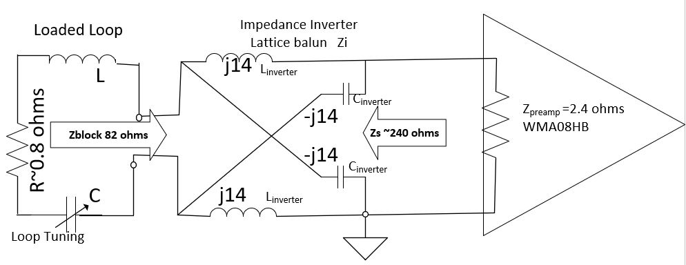
The two-turn, 17.5 cm square loops, spaced from the head by approximately 1 cm of neoprene packaging, exhibited an unloaded to loaded Q ratio of 2.5.The WMA-08HB preamplifier utilized high Q inductors and achieved an input impedance of 2.4 ohms. This yielded an 82-ohm blocking impedance when interfaced with a 14-ohm impedance inverter (Figure 1).
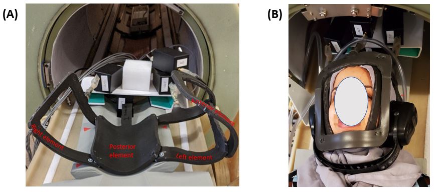
The packaging resulted in a 15 cm square opening for anterior and lateral elements. The elements snap together to set overlaps, and the anterior and a side element are generally left unsnapped until the volunteer is positioned (Figure 2).
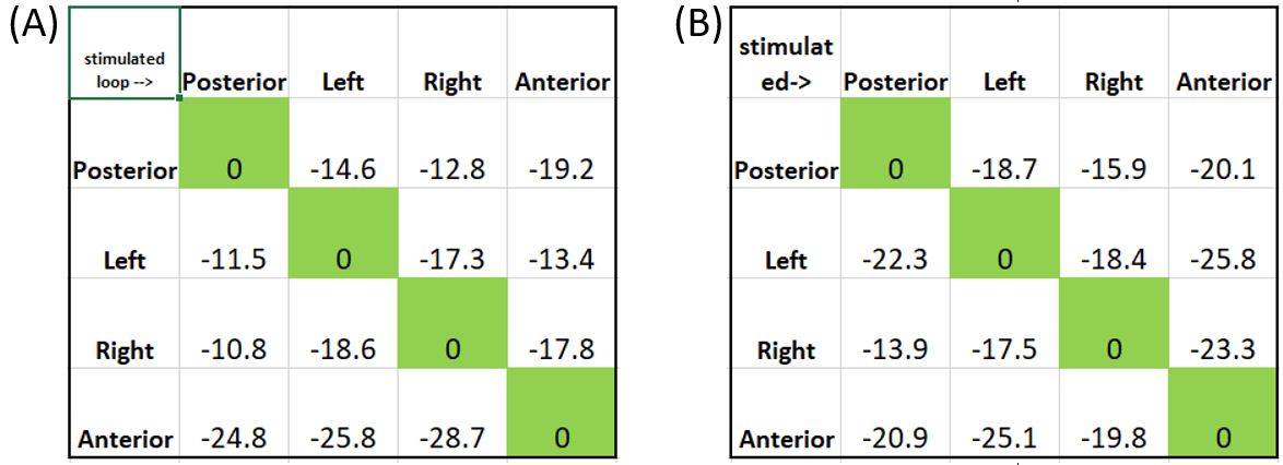
Loop to loop isolation was measured in the 60 cm and 55 cm accommodating over-lap positions (Figure 3).
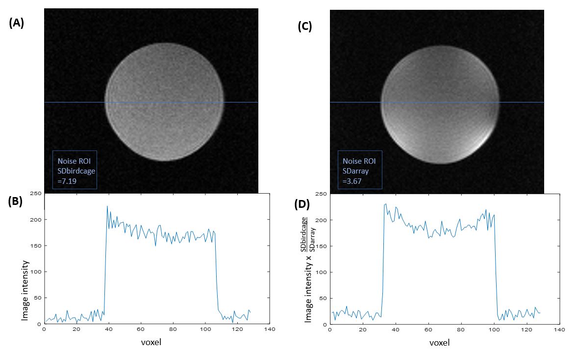
The array SNR at the center of a phantom is improved by approximately 7% versus the quadrature-birdcage coil (Figure 4).
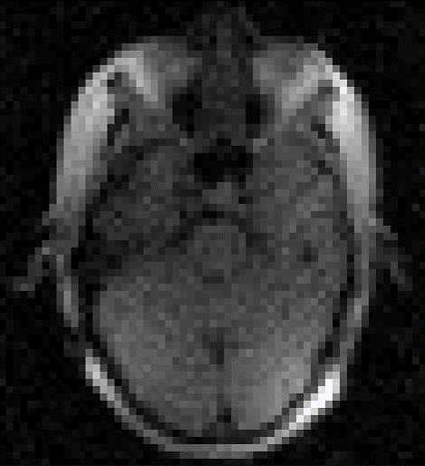
4-channel, healthy volunteer images are now been gathered and evaluated (Figure 5).
Discussion
The loaded to unloaded Q-ratio shows that the coils are in the desired body dominated regime, where SNR losses due to finite loop conductance is minimised.Isolation measurements indicate further improvement in blocking impedance and/or better overlap controls may benefit the array. As expected, the overlaps at the 55 cm coil circumference were closer to the critical overlap and isolation was improved.
In spite of the improved SNR versus the birdcage coil, volunteer image non-uniformity and ringing artifacts need to be investigated and improved to see the array as an overall IQ winner.
Set-up time is very quick, with the array quickly snapping over the volunteer after positioning into the opened array.
Volunteer feedback with the array has been positive. Comfort, openness, and peripheral (headset) compatibility is viewed as generally superior to the birdcage.
Conclusions
A four channel, flexible and open head array been developed for use in in an experimental Field-Cycling Imaging system.Volunteer reaction has been positive, which largely improves experimental conditions for human scans.
With coil and reconstruction improvements, the array has the potential to be the preferred coil for head imaging in the Field-Cycling Imaging system.
Acknowledgements
No acknowledgement found.References
1 Broche LM, Ross PJ, Davies GR, MacLeod MJ, Lurie DJ. A whole-body Fast Field-Cycling scanner for clinical molecular imaging studies. Scientific Reports. 2019;9(1):10402. doi:10.1038/s41598-019-46648-0.
2 Bushby KM, Cole T, Matthews JN, Goodship JA. Centiles for adult head circumference. Arch Dis Child. 1992;67(10):1286-1287. doi:10.1136/adc.67.10.1286.
3 Grafendorfer T, Conolly S, Matter N, Pauly J, Scott G. Optimized Litz Coil Design for Prepolarized Extremity MRI. in 14th ISMRM (Seattle, Washington).
4 Roemer PB, Edelstein WA, Hayes CE, Souza SP, Mueller OM. The NMR phased array. Magn Reson Med (1990) 16:192–225. doi:10.1002/mrm.1910160203
Figures