1898
Development of a Low Field Tabletop Micro-MRI systemUsing Novel Solid-State Hyperpolarization of Water1Physical Measurement Laboratory, National Institute of Standards and Technology, Boulder, CO, United States, 2Advanced Imaging Research Center, UT Southwestern Medical Center, Dallas, TX, United States, 3Chemistry and Biochemistry, The University of Texas at Dallas, Richardson, TX, United States
Synopsis
Micro-MRI systems could have transformational applications in pathology and personalized medicine if substantial technological challenges are overcome: resolution needs to be improved from current state-of-the-art to subcellular resolution <10$$$\mu$$$m, contrast needs to be improved to allow delineation of cells and cell structures, and systems need to be miniaturized from the large high-field superconducting-magnet systems to low-cost tabletop systems. A key enabling component is likely to be a room-temperature low-field point-of-use hyperpolarization system. Here we present a tabletop 135mT micro-MRI system that uses a novel solid-state point-of-use water proton hyperpolarization system integrated into the imaging cell that functions as a bioreactor.
Introduction
Micro-MRI has a long history1 with applications in preclinical imaging, MR histology2, and neurological imaging3. Despite recent advances with demonstrated resolution of 2$$$\mu$$$m4,5, micro-MRI has yet to find widespread application and is unable to compete with optical methods for histology and pathology applications. The lack of applications is driven both by the large size, high cost of current micro-MRI systems as well as the inability to obtain suitable contrast, such as that obtained from H&E stains. Hyperpolarization, similarly, has a long and distinguished history with many techniques, including dynamic nuclear polarization 6-8, optical hyperpolarization of Xe, and nano-diamond9, and continuous Overhauser DNP10 being explored. Many of these systems require high fields, low temperatures, spin with long lifetimes, or introduction of potentially harmful agents. Finally, benchtop NMR and MRI systems11 have now become available capitalizing on powerful better controlled permanent magnet systems and low-cost FPGA-based consoles.Here, we attempt to combine these advances in micro-MRI, hyperpolarization, and benchtop systems to develop pragmatic micro-MRI systems. The use of solid-state ferromagnetic systems utilizing ferromagnetic resonance (FMR) for hyperpolarization remains largely unexplored. High levels of election polarization can be obtained and manipulated at room temperature and low fields using techniques developed for spintronics devices. The transfer of angular momentum per unit volume from the microwaves to the electron system for FMR is given by $$$\frac{\partial S}{\partial t}=\frac{\alpha\sin(\theta)B_{0}M_{S}}{h}\cong\frac{10^{20}h}{\mu m^{3}s}$$$, where $$$\alpha$$$ is the damping constant, $$$\theta$$$ is the precession angle, $$$B_{0}$$$ is the applied field, $$$M_{S}$$$ is the remnant magnetization. The rate of angular momentum transfer is over 10 orders of magnitude greater than what can be done with a paramagnetic agent at room temperature and low fields. Further, effects such as spin pumping allow polarized conduction electrons to be controlled and driven through neighboring nonmagnetic layers12.
Since small, more compact systems are required for use in pathology and personalized medicine applications, we opted for a low field MRI system (135mT) which operates without the use of cryogens, can be miniaturized for point-of-care use and allows the continuous flow hyperpolarization system driven by frequencies between 6GHz and 20GHz where compact low-cost components are available. Given typical tissue perfusion values, tissue volumes ~1mm3 can be perfused without significant loss of polarization.
Methods
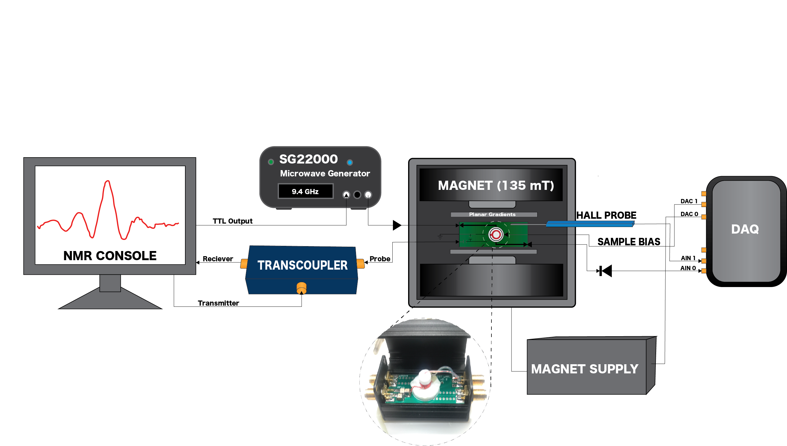
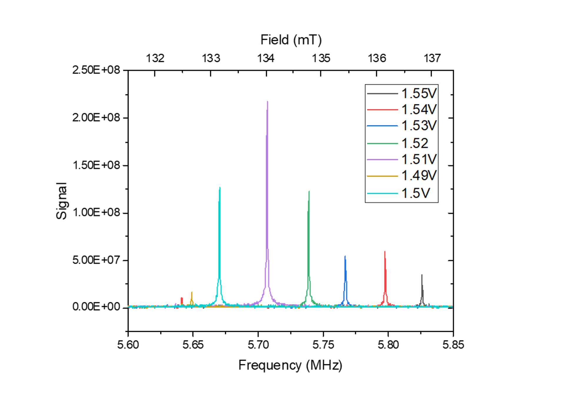
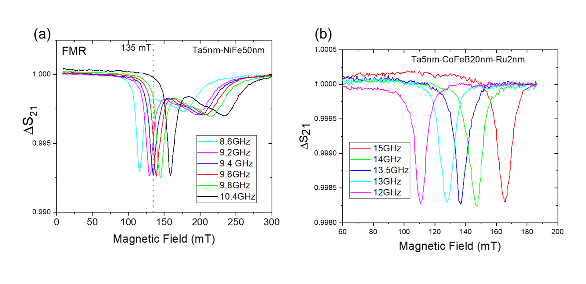
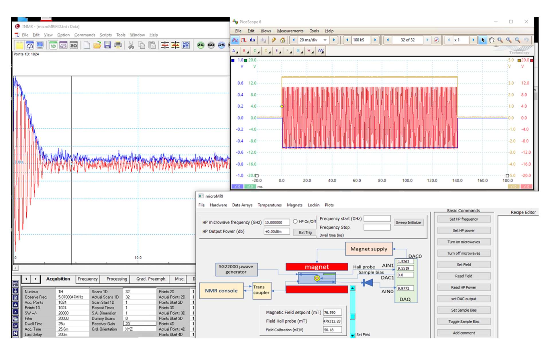
The imaging cell and NMR spectra are shown in Fig. 1 and Fig. 2. The cell is constructed from Teflon with a 3mm diameter sample cell that mates to a standard 3mm biopsy for sample transfer. The base of the cell is formed with an o-ring seal to the ferromagnetic hyperpolarizer film. The ferromagnetic resonance is driven by a coplanar waveguide underneath the film, which is deposited on 12mm diameter 100$$$\mu$$$m thick glass coverslips or 200$$$\mu$$$m thick sapphire disks. The FMR spectra from typical films are shown in Fig. 3, with resonant frequencies varying between 8GHz and 15GHz at the operating field of 135mT. The FMR frequency, which depends on the material composition and magnetic anisotropy energies of the film, was chosen to lie within the range of the compact inexpensive microwave source, amplifier, and waveguide used.The system is run from a commercial NMR/MRI console which can drive a standard high field micro-MRI system (with a 30μm resolution), an electromagnet driven system, or the full miniaturized tabletop micro-MRI. The tabletop magnet system is formed from 50mm diameter NdFeB magnets, soft iron yoke, shaped high permeability pole pieces with B0 shims. The gradients are fabricated using 8-layer printed circuit cards. The RF coil was tuned to ~ 5.7 MHz, the B0 shim was adjusted to get the proton resonance, and the hyperpolarizer frequency was adjusted to be on the center of the FMR peak. We conducted a study of hyperpolarization as a function of microwave frequency and power, as well as hyperpolarizer-sample bias voltage. A screen shot of the pulse sequence is shown in Fig. 4.
Results and Discussion
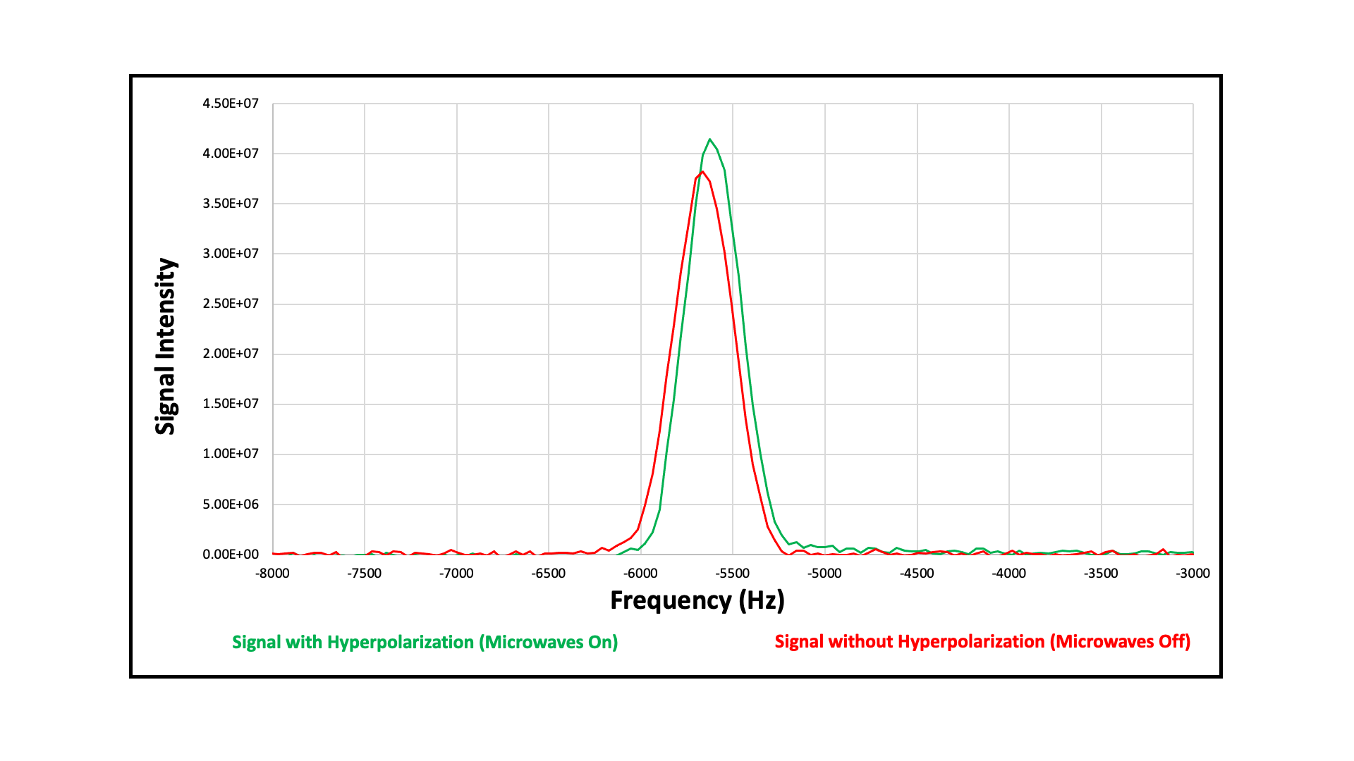
A hyperpolarization sequence was run that compared the strength of the NMR spectra (the integral of the real part of the Fourier transformed free induction decay) with microwaves on and off, various durations of microwave exposure, and various substrate biases. Microwave enhancement studies, Fig. 5, showed modest initial enhancement of 10% to 20%. Strong electrochemical interaction between the bioreactor fluid and the polarizer film, driven by the pulse-sequence controlled sample bias, is observed. The interaction can be destructive with etching or electrodeposition onto the polarizer electrode, but it is thought that this interaction is required for transfer of polarization from the highly polarized electron system to the water protons. The setting of the sample bias waveform and the interfacial spin transport layers of the film stack are the key parameters to vary to improve performance.Conclusion
In summary, we developed a portable, cryogen free, low-cost system for cellular imaging which operates at 135mT. NMR and FMR studies were conducted to optimize the magnet parameters and hyperpolarization studies were performed and showed an initial enhancement of 10% to 20%. Major improvements are required to make this system useful, but initial tests indicate that this may be a promising approach utilizing a new biocompatible integrated hyperpolarization technique.Acknowledgements
We thank Jason Stockman from the Martinos Center for loaning us an MGH designed planar gradient set. We thank the NIST Summer Undergraduate Research Fellowship program for supporting this work. We thank Dr. Dean Sherry and Dr. Zoltan Kovacs for their collaboration and support.References
1. Glover P, Mansfield SP. Limits to magnetic resonance microscopy. Reports on Progress in Physics. 2002;65(10):1489-1511.2. Johnson GA. Magnetic resonance histology. Journal of magnetic resonance imaging : JMRI. 2015;42(1):1-2.
3. Sato C, Sawada K, Wright D, Higashi T, Aoki I. Isotropic 25-Micron 3D Neuroimaging Using ex vivo Microstructural Manganese-Enhanced MRI (MEMRI). Frontiers in Neural Circuits. 2018;12:110.
4. Serša I. Magnetic resonance microscopy of samples with translational symmetry with FOVs smaller than sample size. Scientific reports. 2021;11(1):541.
5. Kresse B, Hofler MV, Privalov AF, Vogel M. One dimensional magnetic resonance microscopy with micrometer resolution in static field gradients. J Magn Reson. 2019;307:106566.
6. Ardenkjaer-Larsen JH, Fridlund B, Gram A, et al. Increase in signal-to-noise ratio of > 10,000 times in liquid-state NMR. Proceedings of the National Academy of Sciences. 2003;100(18):10158-10163.
7. Comment A, Merritt ME. Hyperpolarized Magnetic Resonance as a Sensitive Detector of Metabolic Function. Biochemistry. 2014;53(47):7333-7357.
8. Day SE, Kettunen MI, Gallagher FA, et al. Detecting tumor response to treatment using hyperpolarized 13C magnetic resonance imaging and spectroscopy. Nature Medicine. 2007;13(11):1382-1387.
9. Waddington DEJ, Sarracanie M, Zhang H, et al. Nanodiamond-enhanced MRI via in situ hyperpolarization. Nature communications. 2017;8:15118.
10. Kircher R, Hasse H, Münnemann K. High Flow-Rate Benchtop NMR Spectroscopy Enabled by Continuous Overhauser DNP. Analytical Chemistry. 2021;93(25):8897-8905.
11. Cooley CZ, Stockmann JP, Witzel T, et al. Design and implementation of a low-cost, tabletop MRI scanner for education and research prototyping. J Magn Reson. 2020;310:106625.
12.Tatara G, Mizukami S. Consistent microscopic analysis of spin pumping effects. Physical Review B. 2017;96(6).
Figures