1834
Non-Contrast-Enhanced Whole Neck MR Angiography using Velocity Selective Saturation and Slab Selective Inversion1Division of Mechanical and Biomedical Engineering, Ewha Womans University, Seoul, Korea, Republic of, 2Department of Radiology, Weill Cornell Medicine, New York, NY, United States, 3Department of Biomedical Engineering, Sungkyunkwan University, Suwon, Korea, Republic of, 4Department of Radiology, Seoul National University Hospital, Seoul National University College of Medicine, Seoul, Korea, Republic of, 5Graduate Program in Smart Factory, Ewha Womans University, Seoul, Korea, Republic of, 6Department of Medicine, Case Western Reserve University, Cleveland, OH, United States
Synopsis
Velocity-selective (VS) MRA is a promising non-contrast-enhanced angiography method allowing for high 3D spatial resolution and high angiographic contrast. This study proposes a VS-MRA protocol which includes field error compensation and slab-selective inversion for improved visualization of neck arteries. Initial in-vivo test shows that the proposed VS-MRA better depicts small vessels (such as facial and occipital arteries) and yields higher contrast enhancement ratio than clinical 3D TOF.
Introduction
Velocity-selective (VS) magnetization-prepared imaging is a promising non-contrast-enhanced MRA method. Velocity-selective but spatially non-selective preparation allows for 3D encoding with high spatial resolution in all three dimensions (unlike inflow-based approaches such as TOF [1,2]), and can generate positive angiographic contrast directly from a single acquisition (unlike subtractive 3D approaches [3,4]). Encouraged by great promise of VS-MRA shown in peripheral, renal, pedal, and cerebral arterial territories [5-10], this study aimed to develop VS-MRA protocols for whole neck angiography with initial comparisons with TOF.Methods
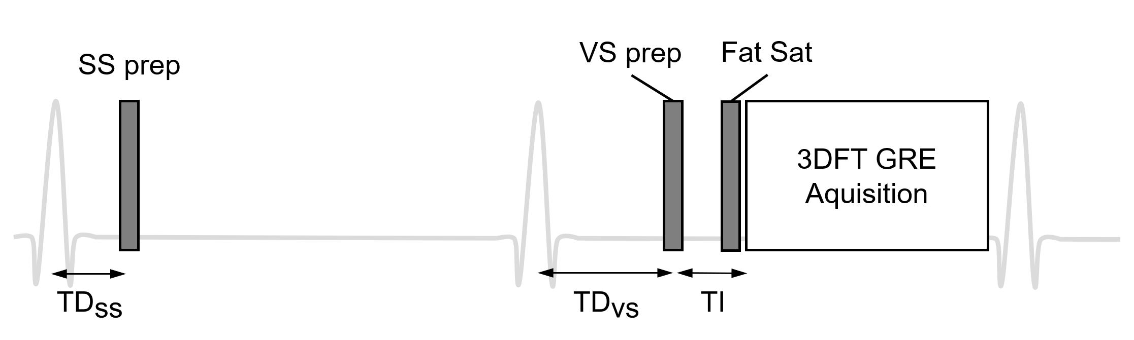
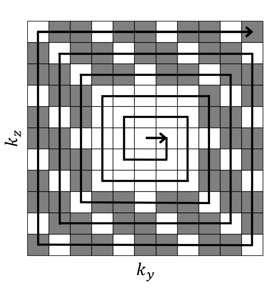
The pulse sequence for the proposed VS-MRA protocol was ECG triggered with a trigger delay (TDss) and applied a slab selective (SS) adiabatic inversion pulse (Figure 1). After the second ECG triggering with a trigger delay (TDvs), velocity selective saturation pulse, a fat saturation pulse, and a 3DFT GRE readout were played sequentially (Figure 1). The SS inversion slab encompassed the imaging volume and extended in the superior direction by 12 cm to invert venous blood which would be suppressed during the data acquisition. Velocity-selective preparation pulse was designed with flip angle = 100°, nine hard RF sub-pulses, velocity FOV = 70cm/s (which resulted in cut-off velocity of 4cm/s) and 90°-180°-90° composite pulses for double refocusing within each velocity encoding step (Figure 2). Based on prior B0 and B1 map measurements in 5 subjects, the VS pulse was pre-compensated through corresponding amplitude and phase modulations. The k-space sampling position was scheduled in a square-spiral fashion to achieve two-dimensional center-out weighting with flexible choice for view-per-segment (Figure 3).3D-TOF (with routine clinical protocol) and VS-MRA were performed for comparison in two healthy volunteers (31-year-old man and 32-year-old man) on a clinical 3T MR scanner (Siemens Medical Solutions). Similar scan time (~10 min), spatial resolution (~0.9×0.9×1.4 mm3), and field of view (220×220×232 mm3) were used. Other TOF parameters were flip angle = 15°, TE/TR = 3.4/20 ms, acceleration factor = 2, number of slabs = 8, slices per slab = 28, and partial Fourier factor = 6/8, 6/8 (slice, phase); Other VS-MRA parameters were flip angle = 14°, TE/TR = 4.6/7.6 ms, acceleration factor = 3, view per segment = 71, repetition time = 3RR, number of slabs = 2, TDss(lower slab/upper slab) = 40/70 ms (beginning of systolic flow) and TDvs(lower slab/upper slab) = 110/140 ms (peak systolic flow). Quantitative image analysis was performed by calculating relative contrast ratio between artery and muscle on manually specified ROIs for eleven arterial segments (1: brachiocephalic artery; 2 and 3: bilateral subclavian arteries; 4 and 5: bilateral common carotid arteries; 6 and 7: bilateral proximal internal carotid arteries; 8 and 9: bilateral cervical segments of the internal carotid arteries; 10 and 11: bilateral petrous segments of the internal carotid arteries).
Results
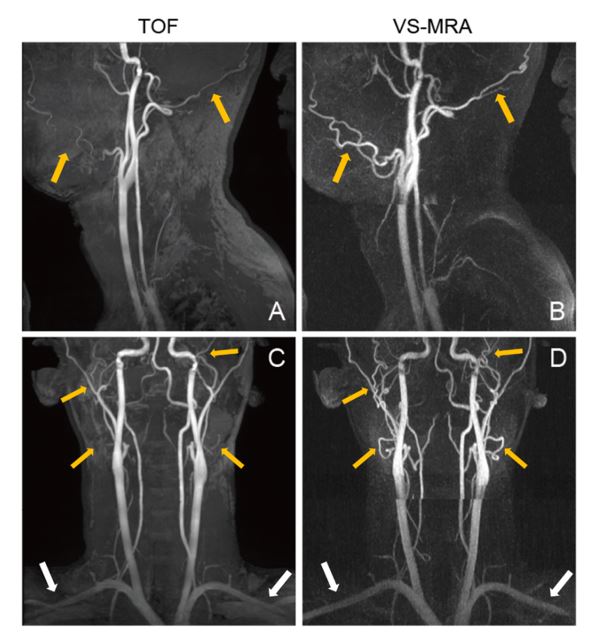
Figure 4 compares VS-MRA with and without B0 and B1 error compensation for VS pulse design (B0 errors measured as 62.3 ± 131.63 / -90.8 ± 78.2 Hz for lower/upper slabs and B1 errors measured as 0.90 ± 0.15 / 1.09 ± 0.11 for lower/upper slabs), showing improved visualization of the subclavian arteries using the pre-compensated VS pulse. Figure 5 shows sagittal and coronal partial MIPs of 3D-TOF and VS-MRA in a healthy subject. While both TOF and VS-MRA well visualize all the major arteries, VS-MRA better depicts relatively small vessels such as facial and occipital arteries due to higher sensitivity to slow flow (yellow arrows). Subclavian arteries are partially suppressed in TOF presumably due to their horizontal orientation, and better captured by VS-MRA (white arrows). Relative contrast ratio was measured as 0.68 ± 0.12 and 0.80 ± 0.10 for 3D-TOF and VS-MRA, respectively.Discussion and Conclusion
We have developed a MRA pulse sequence which combined VS saturation and SS inversion preparation pulses for whole neck angiography. The proposed VS-MRA protocol outperformed the conventional clinical 3D-TOF protocol particularly in visualizing the fine arteries, subclavian artery, and axillary artery due to higher sensitivity to slow flow. Further optimization of VS and SS preparation pulses and comparisons with TOF in a larger group of subjects including patient cohorts with vascular disease will be conducted. Benefit of VS excitation may be even higher in patients, in which blood flow is likely to be slower than healthy subjects.Acknowledgements
This research was supported by Basic Science Research Program through the National Research Foundation of Korea (NRF) funded by the Ministry of Education (NRF-2020R1A6A1A03043528).References
1. Zhang X, Cao YZ, Mu XH, et al. Highly accelerated compressed sensing time-of-flight magnetic resonance angiography may be reliable for diagnosing head and neck arterial steno-occlusive disease: a comparative study with digital subtraction angiography. Eur Radiol. 2020; 30:3059–3065.
2. Davis WL, Blatter DD, Harnsberger HR, Parker DL. Intracranial MR angiography: comparison of single-volume three-dimensional time-of-flight and multiple overlapping thin slab acquisition techniques. American Journal of Roentgenology. 1994;163:915-920.
3. Priest AN, Graves MJ, Lomas DJ. Non-contrast-enhanced vascular magnetic resonance imaging using flow-dependent preparation with subtraction. Magn Reson Med. 2012;67:628-637.
4. Lim RP, Fan Z, Chatterji M, et al. Comparison of nonenhanced MR angiographic subtraction techniques for infragenual arteries at 1.5 T: a preliminary study. Radiology. 2013;267:293- 304.
5. Shin T, Hu BS, Nishimura DG. Off-resonance-robust velocity-selective magnetization preparation for non-contrast-enhanced peripheral MR angiography. Magn Reson Med. 2013;70:1229-1240.
6. Shin T, Menon RG, Thomas RB, et al. Unenhanced velocity‐selective MR angiography (VS‐ MRA): initial clinical evaluation in patients with peripheral artery disease. Journal of Magnetic Resonance Imaging. 2019;49:744-751.
7. Shin T, Worters PW, Hu BS, Nishimura DG. Non-contrast-enhanced renal and abdominal MR angiography using velocity-selective inversion preparation. Magn Reson Med. 2013;69:1268-1275.
8. Watson JDB, Grasu B, Menon R, Pensy R, Crawford RS, Shin T. Novel, non-gadolinium enhanced magnetic resonance imaging technique of pedal artery aneurysms. J Vasc Surg Cases Innov Tech. 2017;3:87-89.
9. Qin Q, Shin T, Schär M, Guo H, Chen H, Qiao Y. Velocity-selective magnetization-prepared non-contrast-enhanced cerebral MR angiography at 3 Tesla: Improved immunity to B0/B1 inhomogeneity. Magn Reson Med. 2016;75:1232-1241.
10. Li W, Xu F, Schär M, et al. Whole‐brain arteriography and venography: Using improved velocity‐selective saturation pulse trains. Magnetic resonance in medicine. 2018;79:2014- 2023.
Figures