1659
Optimization of an RF array for cardiac magnetic resonance at 8.5 MHz1Aberdeen Biomedical Imaging Centre, University of Aberdeen, Aberdeen, United Kingdom, 2GE Healthcare, Waukesha, WI, United States
Synopsis
The SNR and inter coil coupling properties of a range of litz wire coils, in conjunction with the circuitry to match the coils to a low impedance pre-amplifier, were examined. The results of these studies were combined with observations of SNR and coil coupling found in the images of phantoms, obtained with various array designs, to construct an RF array optimized for 0.2 T (8.5 MHz). The array has demonstrated its capability in acquiring cardiac images from human volunteers in our field cycling imager.
Introduction
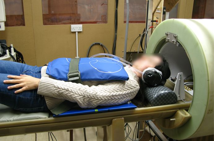
Our group is developing a new imaging technology, Field-Cycling Imaging (FCI), operating at 0.2 T (8.5 MHz)1. For cardiac applications we required an efficient RF receiver. Array receiver technology is common for high field MRI2. but it has had little development below 20 MHz. This work explores the optimisation of the geometry and associated electronics of a variety of single and multiple-loop coils at low field to overcome the challenges of signal performance at cardiac depth, the beating heart and inter-coil coupling. Finally, a 6-element antero-posterior array of 2-turn coils was developed for optimal operation at 8.5 MHz, (Figure 1).Methods
Individual coils, of one to three turns, were wound using litz wire (1600 x 0.020 mm, Elektrisola Co., Reichshof-Eckenhagen, Germany), with a range of diameters from 160 mm to 220 mm. The characteristics of the tuned, unloaded and body-loaded coils were determined through measurements of the Q factor, using a vector network analyser (ZNB 4, Rhode and Schwarz Co. Munich, Germany). The ratio of loaded to unloaded Q factors, Ql and Qu, determined whether the coil noise was body- or coil-dominated. Body noise domination is desirable and was achieved for Qu/Ql > 2.The coils were attached to an electronic circuit on a feed-board shown in Figure 2. This provided: capacitive tuning of the coil to 8.5 MHz for imaging at 0.2 T; impedance matching via a lattice-balun to a low impedance pre-amplifier (WMA08HA - WanTcom Inc., Chanhassen, MN, USA); and active and passive protection of the pre-amplifiers from induced voltages during transmission.
The balun components were selected so that the coil presented optimum impedance for the pre-amplifier to operate at its minimum noise figure, and for the pre-amplifier to provide a high impedance to the coil, thus reducing induced current and consequently the degree of coupling to other coils in an array. The balun also transformed the low impedance of the protection diodes into a high impedance across the coil to protect the electronics.
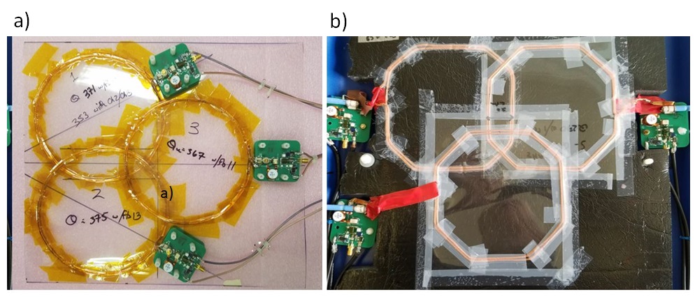
The coupling between pairs of coils, of identical diameter and turn count, was measured as a function of position to determine the optimum geometry with minimal coupling. The coupling was measured by connecting a small coil (ca 5 mm) to the S1 port of a network analyser and using this to drive one of the pair of coils. The signals from the driven and coupled coils were measured at the S2 port of the network analyser. Finally, an RF receiver was constructed for cardiac imaging at 0.2 T as a 6 element, 2-turn, 160 mm antero-posterior array (anterior elements circular, 160 mm in diameter and arranged in a “Venn diagram” pattern with a 40 mm overlap (Figure 3a); posterior elements hexagonal but of the same area and arrangement, Figure 3b).
Spin echo images were acquired of a 75 mM NaCl, 10 mM CuSO4 phantom to determine the sensitivity map and SNR of each coil and array assembly. Further, as proof-of-concept we acquired cardiac images from three human volunteers. Images were collected with an ECG-gated spin echo pulse sequence with a matrix size of 80 x 80, acquisition bandwidth of 33.3 kHz, 460 mm field of view, TE of 22 ms, slice thickness of 15 mm and in-plane resolution of 5.75 mm.
Results and discussion
Qu, Ql and their ratios are shown for the coils studied in Table 1. For the single turn coil the ratio was as low as 2.2. We therefore rejected a single loop design for low field applications.| Coil | QU | QL | QU/QL |
| 1-turn 160 mm | 225 | 101 | 2.2 |
| 2-turn 160 mm | 362 | 85 | 4.3 |
| 3-turn 160 mm | 520 | 150 | 3.5 |
| 2-turn 220 mm | 380 | 130 | 2.9 |
Table 1: Q factors and ratios of the coils.
The results in Table 2 show that whilst the sensitivity of an element in an array could be increased by increasing the number of turns there was a penalty with the increased coupling to other elements. As the 2-turn 220 mm coil had shown poor performance in the imaging of phantoms a second coil of this type was not constructed and coupling between two such coils was not investigated.
| | 2-turn 160 mm diameter coils | 3-turn 160 mm diameter coils |
| Coupling (dB) | ||
| With optimum overlap | -33.0 +/- 1 | -33.5 +/- 1 |
| With 300 mm coaxial separation | -35.0 +/- 1 | -27.0 +/- 1 |
Table 2: Coupling between pairs of coils.
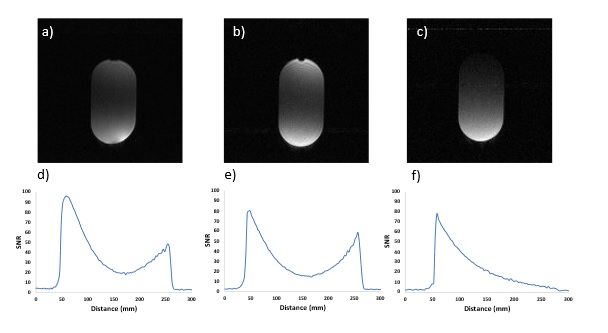
The 3-turn 160 mm coils and the 2-turn 220 mm coil were initially found to have greater sensitivity than the 2-turn 160 mm coil. However, when a further 36 dB of pre-amplifier gain was introduced into the signal train between the feed-board and the console the 2-turn 160 mm coil demonstrated the best SNR (Figure 4), indicating greater inherent SNR though lower overall signal level in the 2-turn 160 mm coil.
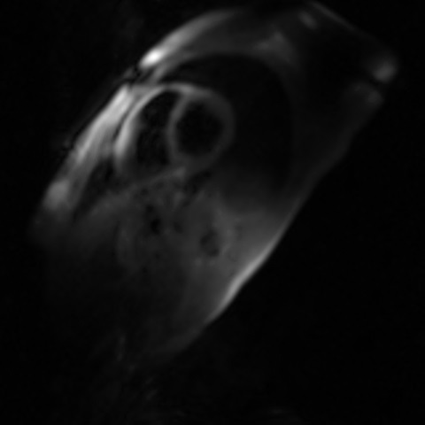
The Antero-posterior array was found to be the only arrangement with sufficient SNR to obtain short axis cardiac images (Figure 5).
Conclusion
We have constructed an RF coil array optimised for low-field imaging and successfully demonstrated that it can be used to acquire cardiac images from human volunteers. This paves the way for future research on low field and field-cycling cardiac imaging.Acknowledgements
This research was supported by the British Heart Foundation through a New Horizons grant NH/19/1/34595.References
1) Broche, L., Ross, P. J., Davies, G. R., Macleod, M-J., & Lurie, D. J. (2019). A whole-body Fast Field-Cycling scanner for clinical molecular imaging studies. Scientific Reports, 9, [10402]. https://doi.org/10.1038/s41598-019-46648-0
2) Roemer P, Edelstein W, Hayes C, Souza S, Mueller O. (1990). The NMR Phased Array. Magnetic Resonance in Medicine 16; 192-225
Figures