1658
Active Catheter Tracking Error Characterization for Minimally Invasive MR-Guided Cardiac Interventions1Department of Medical Biophysics, University of Toronto, Toronto, ON, Canada, 2Physical Science Platform, Sunnybrook Research Institute, Toronto, ON, Canada, 3Schulich Heart Program, Sunnybrook Research Institute, Toronto, ON, Canada
Synopsis
Minimally invasive cardiac interventions, such as ablation treatment for ventricular tachycardia and therapy delivery involving biologics (cells, genes, biomaterials) for the treatment of myocardial infarction, require a tracking accuracy of <5mm. Our study aimed to characterize the spatial error associated with MR-guided active catheter tracking under static conditions. In a 1.5T MR scanner, we tracked an ablation catheter at 48 different positions, all confined within the boundaries of where a typical human heart would be located. We found that the error was both minimized and maintained below our 5mm target when using a Hadamard multiplexed active tracking sequence.
Background
Magnetic resonance imaging (MRI) is a promising image guidance modality for minimally invasive cardiac interventions. Some examples of such catheter-based interventions include radiofrequency (RF) ablation treatment for ventricular tachycardia, and therapy delivery involving biologics (cells, genes, biomaterials) for the treatment of myocardial infarction [1]. Studies in the past have had success with MR-guided RF ablations in left ventricular myocardium [2] and have also shown feasibility with transendocardial cell delivery [3], but have not characterized the errors associated with MR-guided catheter positioning within the heart. Recent electrophysiology (EP) work has shown that a targeting accuracy of <5mm is desired for RF ablations, since re-entry circuits are generally situated within 5mm of infarct border zones [4]. Additionally, prior work demonstrated that a 1cm injection spacing pattern maximized the retention of injected pluripotent stem cell-derived cardiomyocytes in non-human primate hearts [5]. Given these results, a target of constraining tracking error to <5mm is warranted. Hence, the aim of our study was to characterize the errors associated with MR-guided active catheter tracking under static conditions, using a phantom setup and two different types of pulse sequences.Methods
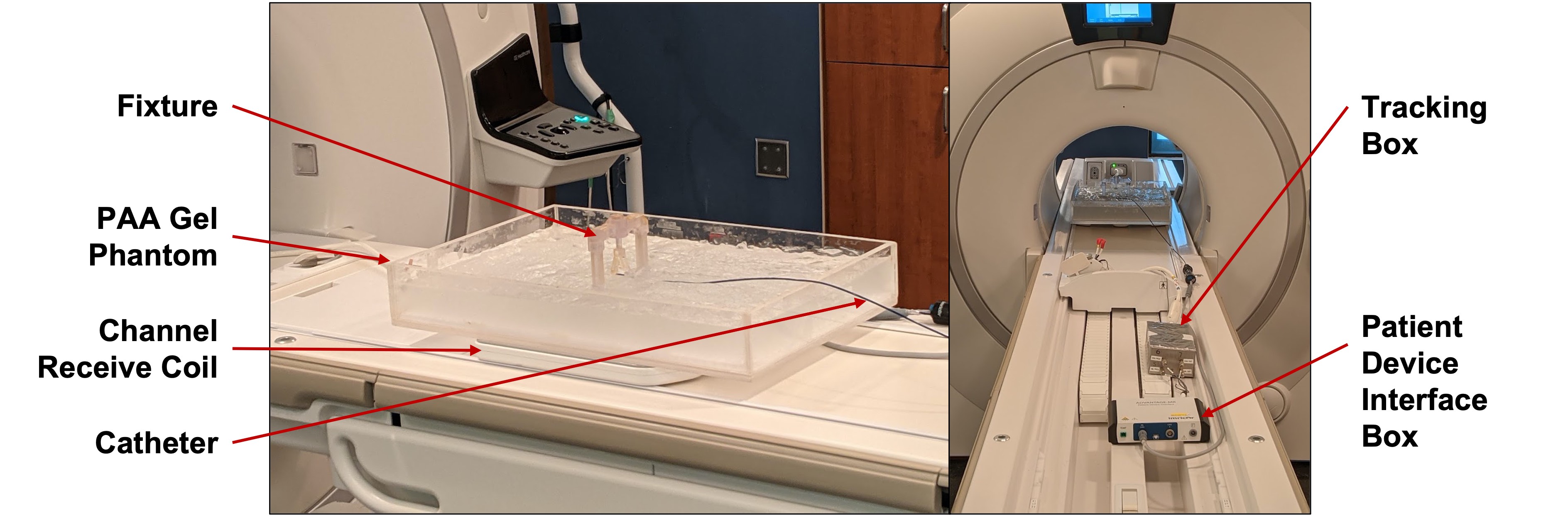
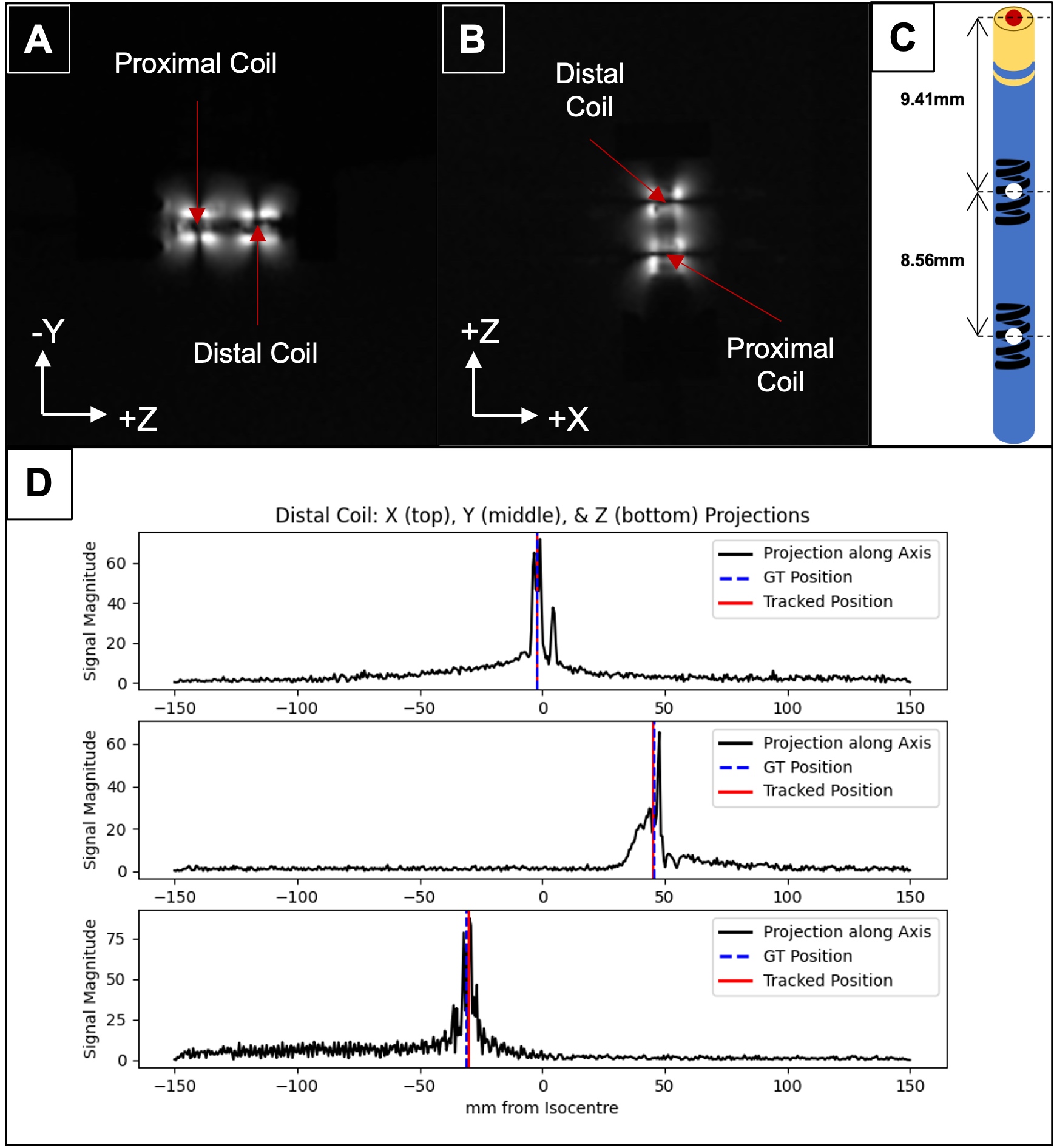
The tracking setup is shown in Figure 1. The 9F ablation catheter (Vision-MR, Imricor Medical Systems) has two microcoils embedded at its distal end, which allows for active tracking under MRI. Using both conventional 3-projection [6] (Flip angle = 5°; FOV = 30 x 30 x 30cm; acquisition size = 512; TR = 9ms) and Hadamard multiplexed [6] (Flip angle = 5°; FOV = 17.3 x 17.3 x 17.3cm; acquisition size = 256; TR = 2ms) active tracking sequences, implemented in RTHawk (HeartVista Inc.) in a 1.5-T MR scanner (MR450w, General Electric), we tracked the catheter tip (extrapolated from the coil positions – see Fig 2) at 16 positions within a saline and polyacrylic acid gel phantom. The 16 positions were mainly constrained to the (+X, +Z) quadrant of the X/Z plane, within the boundaries of X < 100mm and Z < 80mm. The gel phantom’s positioning along the Y-axis was varied as well, so that tracking could be repeated for each of the 16 X/Z positions at three different elevations (Y = -5mm, 20mm, 45mm). These boundaries were chosen to encompass the likely location of the human heart during a scan. A fixture was used to maintain tip alignment with the main magnetic field at each position. Separate studies demonstrated relative orientation independence of measures. We acquired both ground truth imaging data and 15 seconds of real-time tracking data at each position. Error was calculated as the absolute difference between the ground truth coordinate and the mean tracked coordinate.Results
Ground truth coronal and sagittal slices of the catheter tip at one position are presented (Fig 2), along with heat maps of catheter tip tracking error at the 16 X/Z positions, for each of the three Y elevations (Fig 3). The main results are summarized below.At Y = -5mm: With the conventional sequence, the mean error was 2.34 ± 0.009mm, while the min and max errors were 0.75 ± 0.009mm and 4.72 ± 0.02mm, respectively. With Hadamard multiplexing, the mean error was 1.59 ± 0.02mm, while the min and max errors were 0.60 ± 0.005mm and 3.18 ± 0.02mm, respectively.
At Y = 20mm: With the conventional sequence, the mean error was 2.28 ± 0.02mm, while the min and max errors were 0.50 ± 0.003mm and 4.28 ± 0.06mm, respectively. With Hadamard multiplexing, the mean error was 1.61 ± 0.03mm, while the min and max errors were 0.59 ± 0.05mm and 3.63 ± 0.02mm, respectively.
At Y = 45mm: With the conventional sequence, the mean error was 3.33 ± 0.02mm, while the min and max errors were 0.91 ± 0.003mm and 11.67 ± 0.08mm, respectively. With Hadamard multiplexing, the mean error was 1.64 ± 0.08mm, while the min and max errors were 0.60 ± 0.04mm and 3.37 ± 0.12mm, respectively.
The error observed with Hadamard multiplexing was generally lower than that observed with the conventional sequence, and was always maintained below our target constraint of 5mm.
Conclusions
For active catheter tracking under static conditions, employing Hadamard multiplexing was preferable to using the conventional sequence as the former is, by design, insensitive to off-resonance errors due to static magnetic field inhomogeneities. Our next step is to characterize the tip tracking error under dynamic conditions (using a motion phantom) to simulate cardiac and respiratory motion. In vivo conditions will introduce additional error sources, notably relative tissue motion; however, our study confirms that static tracking errors should not be limiting for the 5mm target accuracy, encouraging next steps toward in vivo translation for applications involving MR-guided cardiac EP and delivery of biologics.Acknowledgements
We acknowledge the funding support from the New Frontiers in Research Fund – Exploration, the Ontario Research Fund, and the University of Toronto’s Medicine by Design initiative which receives funding from the Canada First Research Excellence Fund. We also acknowledge research support from HeartVista Inc., GE Healthcare, and Imricor Medical Systems. Arjun Gupta is supported by the Queen Elizabeth II Graduate Scholarship in Science and Technology. Dr. Nilesh Ghugre is supported by the National New Investigator award from the Heart and Stroke Foundation of Canada.References
1. Wang, W. MR Guided Active Catheter Tracking. Magn. Reson. Imaging Clin. N. Am. 23, 579–589 (2015).
2. Chubb, H. et al. Cardiac Electrophysiology Under MRI Guidance: an Emerging Technology. Arrhythmia Electrophysiol. Rev. 6, 85 (2017).
3. Dick, A. J. et al. Magnetic Resonance Fluoroscopy Allows Targeted Delivery of Mesenchymal Stem Cells to Infarct Borders in Swine. Circulation 108, 2899–2904 (2003).
4. Piers, S. R. D. et al. CMR–Based Identification of Critical Isthmus Sites of Ischemic and Nonischemic Ventricular Tachycardia. JACC Cardiovasc. Imaging 7, 774–784 (2014).
5. Chong, J. J. H. et al. Human Embryonic Stem Cell-Derived Cardiomyocytes Regenerate Non-Human Primate Hearts. Nature 510, 273–277 (2014).
6. Dumoulin, C. L., Souza, S. P. & Darrow, R. D. Real-time position monitoring of invasive devices using magnetic resonance. Magn. Reson. Med. 29, 411–415 (1993).
Figures