1615
MRI with Sub-Millisecond Temporal Resolution: SPIRE Imaging of a High-speed Motion Phantom
1Dept. of Radiology, Medical Physics, Medical Center University of Freiburg, Faculty of Medicine, Uni, Freiburg, Germany
Synopsis
Imaging sequences with sub-millisecond temporal resolution based on single point imaging (SPI) are very time inefficient. We designed and imaged a motion phantom capable of velocities up to 5.5m/s. A synchronization signal is acquired using a photoelectric barrier and combined with a sequence trigger signal. Reconstructed images show clear delineation of small structures with a spatial resolution of $$$\Delta x$$$=0.67mm and a temporal resolution of $$$\delta t$$$=246μs.
Introduction
Recently, MRI sequences have been developed which can visualize rapid 2D motion with sub-millisecond temporal resolution, e.g. of the vocal folds [1], heart valves [2], or electrical signals [3]. Our implementation, the SPIRE sequence [1], uses single point imaging (SPI) leading to long measurement times, so that volunteer measurements can become challenging. To assess the precision of SPIRE, a motion phantom is required that offers motion velocities up to 5m/s as can be found in the vocal folds [4]. Here, we present a custom-built, MR-compatible rotation phantom to demonstrate the imaging capabilities of SPIRE.Methods and Materials
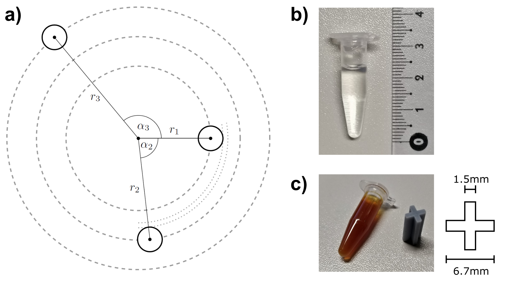
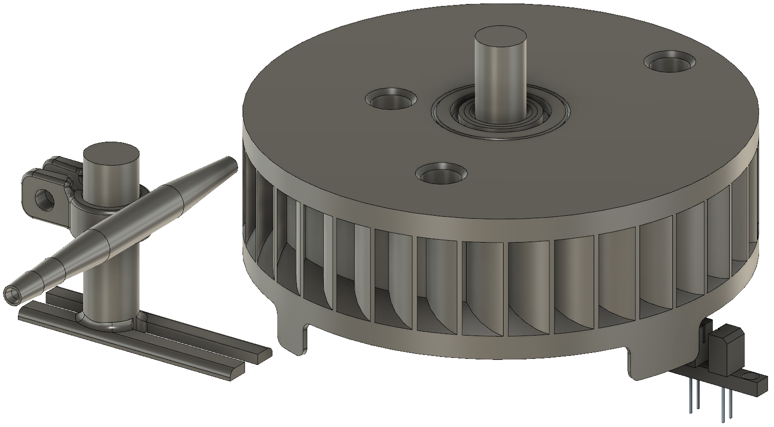
To create a repeatable angular motion, a rotation phantom was constructed with small tubes of equal mass $$$m$$$ (V=0.5 mL, ∅o=7.5 mm) that are placed at different radii $$$r_i$$$ and that can be filled with contrast media solutions. The placement at different $$$r_i$$$ allows for simultaneous measurements at different velocities and avoids signal ambiguities as the samples move along different trajectories for each rotation. To reduce vibrations at high angular frequencies, the mass distribution in the phantom was balanced such that the center of mass coincides with the rotation axis: $$\vec{CM}=\sum_i^N\frac{m\vec{r_i}}{M}=\frac{1}{N}\sum_i^N\vec{r_i}=\frac{1}{N}\sum_i^N r_i\left(\begin{array}{c} \cos(\alpha_i) \\ \sin(\alpha_i)\end{array}\right)=\left(\begin{array}{c} 0 \\ 0\end{array}\right)$$ For $$$N$$$=3 tubes and a constant distance $$$\Delta r$$$ between the radii this yields the conditions $$\frac{r_1+r_3}{2}=r_2$$ and (with $$$\alpha_1$$$=0°) $$\cos{\alpha_2} = \frac{3(r_1+r_3)}{4r_1}-2$$ $$\cos{\alpha_3} = 1-\frac{3(r_1+r_3)^2}{8r_1r_3}.$$ With $$$r_1$$$=22mm, $$$r_2$$$=31mm and $$$r_3$$$=40 mm ($$$\Delta r$$$=9 mm) the radial separation between the samples is 1.5 mm and the angles are $$$\alpha_2$$$=83.5° and $$$\alpha_3$$$=129.6°. A schematic of the phantom can be seen in figure 1. To rotate the disk with the samples, compressed air is blown into the blades of the phantom. As the SPIRE image reconstruction requires information about the phantom’s rotation angle, 4 shutters are attached below the disk that periodically close a photoelectric-barrier. The main body of the phantom (Fig. 2) was 3D-printed in polylactic acid (PLA) on a fused deposition modelling printer (Prusa i3 Mk3S, Prusa Research) and is held in place in a frame made from plastic sheets. The rotation axis is attached with ball bearings made of polyetheretherketon (PEEK), as ceramic bearings can create image artefacts. The photoelectric barrier is powered by a non-magnetic 9V battery inside the bore. The electric signal from the barrier is transported via a coaxial cable which was equipped with baluns to reduce RF coupling. It is recorded together with a synchronization signal from the MR sequence that is created during the RF pulse with a stand-alone PC running audio-recording software (Audacity, Audacity Team). In the reconstruction, time delays between signal edges are detected to determine the phase of the rotation in each TR, as well as the rotation frequency. The material in the sample tubes comprises distilled water and contrast agent (Prohance) to obtain $$$T_1\approx$$$100ms. Agar agar is added to solidify the mixture in order to prevent artefacts from turbulence. Bacterial growth is prohibited by the addition of ethanol (Figure 1b). To allow for the analysis of higher spatial resolution, small inserts can be placed in the tubes which have a thickness of 1.5 mm (Figure 1c). The inserts were printed with photoreactive resin using masked stereolithography (Prusa SL1, Prusa Research). As the largest radius defines the necessary imaging FOV and, thus, the duration of the measurement the outer sample tubes can be replaced by MR-invisible samples to reduce measurement time. These samples were prepared with a negative contrast agent (Resovist) which reduced $$${T_2}^*<$$$1 ms (Figure 1c). SPIRE images with a maximum phase encoding duration of 800μs were acquired of one visible high-resolution sample at $$$r_1$$$=22mm rotating at a target frequency of 40 Hz ($$$v_{tangential}$$$=5.5 m/s). Other imaging parameters were: FOV=60x60mm2, $$$\Delta x$$$=0.667mm, TE/TR=1.15/2.96ms, a=8°, TA=40min). Using the synchronization signals, the SPIRE data was sorted into 100 time frames (i.e., 3.6° angular resolution) and reconstructed using a total variation constraint along the temporal dimension [5].Results
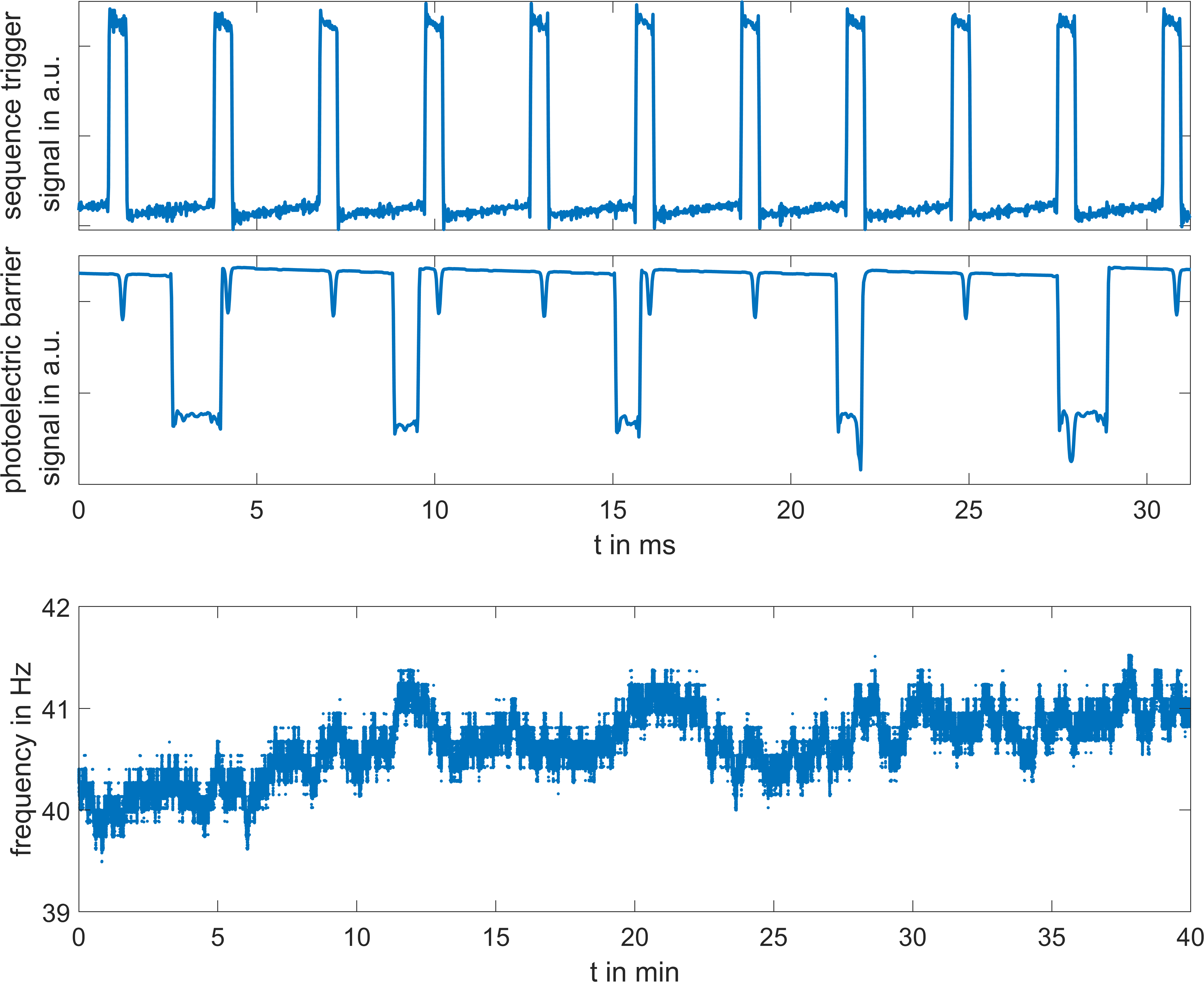
In Figure 3 exemplary signals from both the MR sequence and the optical are shown. In this experiment the rotation frequency was very stable with $$$f$$$ = 40.7($$$\pm$$$0.3) Hz, exhibiting only a small drift over the total measurement time which might be attributed to small variations in the supplied air pressure. For 100 reconstructed frames this results in a temporal resolution of 246$$$\pm$$$2μs and the images clearly show the motion of the phantom as well as internal structures. With a radius of 22mm the tangential motion velocity was $$$v$$$=5.6 m/s.Discussion
During measurement setup, the rotational center can be difficult to identify and may lead to off-center FOV which has to be corrected in the reconstruction. This could be improved with an MR visible filling of the axis. Although the longest phase encoding duration in the SPIRE acquisition was more than 3x longer than the reconstructed resolution, even small internal structures of the sample tubes could be well resolved – this result shows that SPIRE can image very rapid motion reconstructed at smaller temporal resolution than the duration of phase encoding gradients.Acknowledgements
References
[1] J. Fischer et al., “Sub-millisecond 2D MRI of the vocal fold oscillation using single-point imaging with rapid encoding,” Magn Reson Mater Phy, Sep. 2021, doi: 10.1007/s10334-021-00959-4.
[2] Z. Zhong et al., “Visualization of Human Aortic Valve Dynamics Using Magnetic Resonance Imaging with Sub-Millisecond Temporal Resolution,” Journal of Magnetic Resonance Imaging, vol. 54, no. 4, pp. 1246–1254, 2021, doi: 10.1002/jmri.27603.
[3] C. J. G. Bakker et al., “Multiple single-point imaging (mSPI) as a tool for capturing and characterizing MR signals and repetitive signal disturbances with high temporal resolution: The MRI scanner as a high-speed camera,” Magnetic Resonance Imaging, vol. 31, no. 7, pp. 1037–1043, Sep. 2013, doi: 10.1016/j.mri.2013.04.014.
[4] Y. W. Shau, C. L. Wang, F. J. Hsieh, and T. Y. Hsiao, “Noninvasive assessment of vocal fold mucosal wave velocity using color doppler imaging,” Ultrasound Med Biol, vol. 27, no. 11, Art. no. 11, Nov. 2001, doi: 10.1016/s0301-5629(01)00453-7.
[5] M. Uecker et al., “Berkeley Advanced Reconstruction Toolbox,” in In Proc. Intl. Soc. Mag. Reson. Med., Toronto, 2015, vol. 23, p. 2486.
Figures