1570
Scalable and Modular 8-Channel Transmit and 8-Channel Flexible Receive Coil Array for 19F-MRI of Myocardial Infarction Studies in Large Animals1Dept. Radiology, Medical Physics, Medical Center - University of Freiburg, Freiburg, Germany, 2Cardiology and Angiology I, Heart Center Freiburg University and Faculty of Medicine, Freiburg, Germany, 3Neurozentrum, Wissenschaftliche Werkstätten, Medical Center - University of Freiburg, Freiburg, Germany
Synopsis
In this study, we have developed an 8-channel transmit/ 8-channel receive coil array system for cardiac and thoracic MRI in pigs. Transmit array is scalable in size to increase transmit efficiency in pigs with smaller abdomen size. Receive array is semi-flexible to fit tightly on the dome-shaped thorax of pigs. We present a detailed transmit efficiency analysis of the Tx array including tolerance to mismatches at the input ports. We also present 19F MRI results from a cadaver measurement.
Introduction
19F-MRI has been applied in rodents to study myeloid cell uptake and migration after myocardial infarction[1]–[5], but it has rarely been used in human-size models such as pigs[4]; however, large animal studies are crucial for method development and validation of clinical applications. The purpose of this study is to improve the 19F RF coil system designed for cardiac and splenic MRI at 3T[6] by a size-adaptive, modular Tx array unit and to provide a detailed performance analysis. Measurements and FDTD simulations are performed for a 19F grid phantom and 3D-rendered animal models and a cadaver experiment was conducted.Methods
A 19F RF coil system was designed and tested for cell tracking in pigs with consists of an 8-element Tx coil array, and an 8-element Rx surface coil set[6] distributed to anterior and posterior parts (Fig.1a). All coil elements were designed to be resonant only at the 19F Larmor frequency at 3T(115.9MHz). The Tx coil consists of 8 independent loop coils (size:6x15cm², Fig.1d) symmetrically arranged in a circle (Ø=42cm), 5 of which are fixed on a detachable upper section (Fig.1c). The diameter of the Tx array can be adapted to the animal using 3D-printed spacers that attach to the inner surface of the coil holder. The 3T MRI system (Prisma Fit, Siemens, Germany) provides up to 3kW peak RF power at 115.9MHz. An 8-way Wilkinson divider was designed to split the power equally to each channel (Fig.1e), and 45° phase shifters were added to operate the coil in circular polarization(CP). S-parameters Sij, B1+-homogeneity, and transmit-efficiency of the Tx coil were measured.Electromagnetic field simulations were performed using the FDTD solver of Sim4Life 6.2 (ZMT, Zurich, CH) to assess the effects of animal size (small/large), coil arrangement (small/large Fig.3d,e), amplitude and phase mismatches (random deviations within 20% of the CP mode) in the Tx array elements on the B1+-homogeneity, Tx-efficiency and the maximum peak local SAR.
B1+-homogeneity was evaluated along three lines across the heart of the pig models (Fig.2e). The results were normalized for total of 3kW input power. An additional simulation was performed to validate the grid-phantom measurements for B1+-homogeneity.
As 19F-based phantom liquids are costly and often have dielectric properties that differ from that of human tissue, a grid phantom was constructed in which perfluorpolyether is arranged in a grid of tubes. To match the dielectric constant to that of human tissue, the remaining phantom body was filled with 13.6L distilled water with 3g/L NaCl and 1g/L CuSO4 (Fig.3f). To evaluate SNR and B1+ homogeneity, 3D GRE images (2x2mm2, Slice-thickness=4mm, TR/TE=20/4ms, FA=15°/30°, 128x128 matrix) were acquired. B1 maps were calculated using the double-angle-method [8].
Finally, a bottle of perfluoroctylbromide (PFOB) was inserted in the thorax of a pig cadaver, replacing the excised heart. 19F 3D GRE data were acquired (TR/TE=5/1.4ms, FA=20°, 2x2x4mm3, 384x384 matrix, 48 slices, Navg=10) in total acquisition time of 11:24min:s and co-registered to 1H MPRAGE images.
Results
S-matrix measured with phantom loading shows that the isolation between the Tx elements are higher than 13dB and the input impedance of each coil is close to 50W (Fig.3a-c). Wilkinson divider has an additional insertion loss up to 1.5dB at the output ports. Using the coil arrangement with smaller diameter for a smaller phantom loading (Fig.3b) improves reflection coefficients by up to 5.7dB compared to the larger coil diameter (Fig.3c) due to improved loading.In Fig.4, B1+ maps for various pig and coil pairs are shown for a transverse slice across the center of the heart. Using 7 and 5-channel coils increases Tx-efficiency in the region of the heart. For the smaller pig model, a smaller coil (SPSC) increases Tx-efficiency by 40% compared to the SPLC case. Quadrature birdcage coils have higher Tx-efficiency for both small and large pigs. The B1+ line profile analysis showed that the Tx homogeneity is better than 30% for all cases except for LPLC, where up to 45% deviation from the mean is observed along L1 (head-foot). Field combinations with 20% random deviations from CP resulted in less than 6% deviation in B1+-homogeneity. For the smaller pig, birdcage and the smaller coil array have superior homogeneity in the longitudinal direction. Grid phantom simulations (results not shown) confirm that the 19F signal from the tubes distributed over regular phantom reflects the coil homogeneity.
In Fig.5, 19F image from the PFOB liquid inside the thorax of the pig cadaver is overlaid on the 1H image. PFOB comprises several resonances, thus, chemical shift artefacts are observed along the readout direction. SNR of the three spectrally separated 19F components are 22, 44.2, and 28.3.
Discussion
FDTD simulations showed that the Tx array is robust against phase and power deviations at the input ports. Although the Tx-efficiency of quadrature birdcage coils are higher than the Tx array, the modular, scalable Tx array has advantages of simplicity (3D printed no electrical or mechanical connection between the elements, each element can be tuned individually), potential use with parallel Tx and ease of handling. Unlike birdcage coils, this coil can also be adapted to higher fields after retuning, without further modificationsAcknowledgements
Grant support by the German Science Foundation (DFG) under CRC 1425 (Project P15) is gratefully acknowledged.
We also thank Dominik von Elverfeldt from Universitätsklinikum Freiburg and Muhammed Yildirim of University of Cologne for fruitful discussions on 19F substances and phantom design.
References
[1] M. Nahrendorf, M. J. Pittet, and F. K. Swirski, “Monocytes: protagonists of infarct inflammation and repair after myocardial infarction.,” Circulation, vol. 121, no. 22, pp. 2437–45, Jun. 2010, doi: 10.1161/CIRCULATIONAHA.109.916346.
[2] M. Nahrendorf and F. K. Swirski, “Monocyte and macrophage heterogeneity in the heart.,” Circ. Res., vol. 112, no. 12, pp. 1624–33, Jun. 2013, doi: 10.1161/CIRCRESAHA.113.300890.
[3] S. Temme et al., “Technical advance: monitoring the trafficking of neutrophil granulocytes and monocytes during the course of tissue inflammation by noninvasive 19F MRI.,” J. Leukoc. Biol., vol. 95, no. 4, pp. 689–97, Apr. 2014, doi: 10.1189/jlb.0113032.
[4] F. Bönner et al., “Monocyte imaging after myocardial infarction with 19F MRI at 3 T: a pilot study in explanted porcine hearts.,” Eur. Heart J. Cardiovasc. Imaging, vol. 16, no. 6, pp. 612–20, Jun. 2015, doi: 10.1093/ehjci/jev008.
[5] H. Amiri, M. Srinivas, A. Veltien, M. J. van Uden, I. J. M. de Vries, and A. Heerschap, “Cell tracking using (19)F magnetic resonance imaging: technical aspects and challenges towards clinical applications.,” Eur. Radiol., vol. 25, no. 3, pp. 726–35, Mar. 2015, doi: 10.1007/s00330-014-3474-5.
[6] A. C. Özen, F. Spreter, T. Heidt, C. von zur Mühlen, and M. Bock, “A Dedicated RF Coil System for 19F MRI of Myocardial Infarction at a 3 T Clinical MRI System,” in Proc. Intl. Soc. Mag. Reson. Med. 29, 2021, p. 1809.
[7] A. Fedorov et al., “3D Slicer as an image computing platform for the Quantitative Imaging Network.,” Magn. Reson. Imaging, vol. 30, no. 9, pp. 1323–41, Nov. 2012, doi: 10.1016/j.mri.2012.05.001.
[8] F. Balezeau, P.-A. Eliat, A. B. Cayamo, and H. Saint-Jalmes, “Mapping of low flip angles in magnetic resonance.,” Phys. Med. Biol., vol. 56, no. 20, pp. 6635–47, Oct. 2011, doi: 10.1088/0031-9155/56/20/008.
[9] G. Carluccio, C. Akgun, J. T. Vaughan, and C. Collins, “Temperature‐based MRI safety simulations with a limited number of tissues,” Magn. Reson. Med., vol. 86, no. 1, pp. 543–550, Jul. 2021, doi: 10.1002/mrm.28693.
Figures
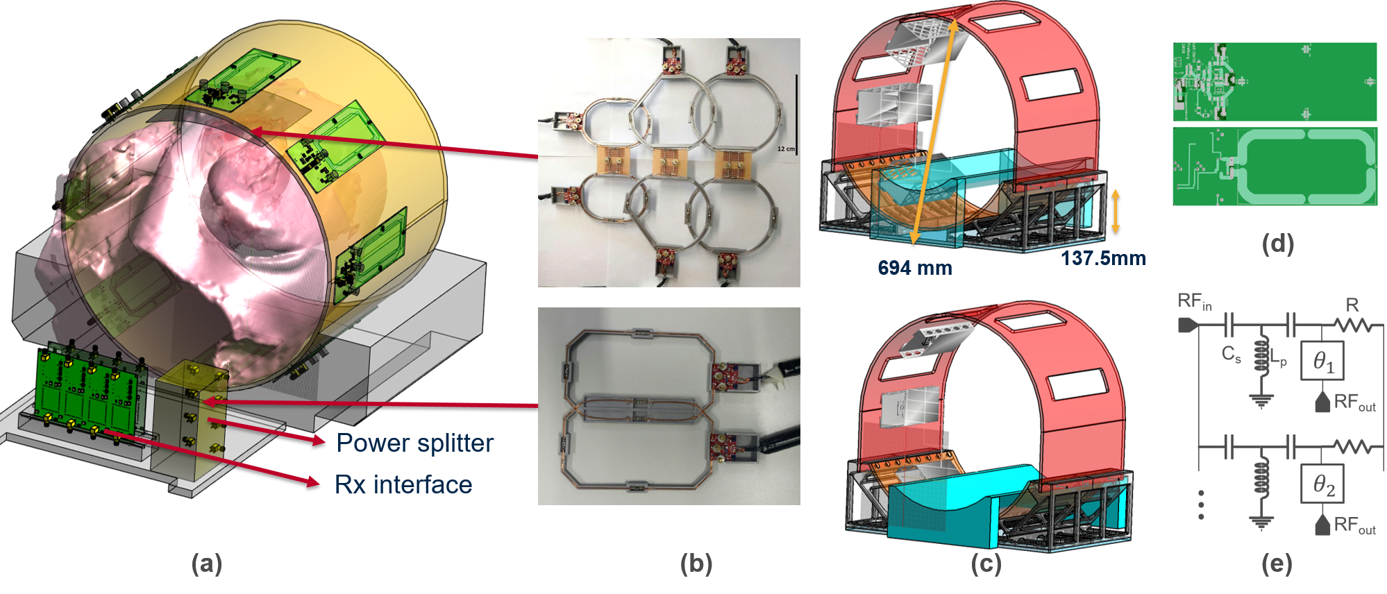
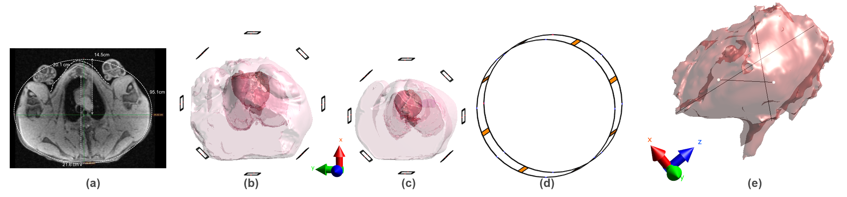
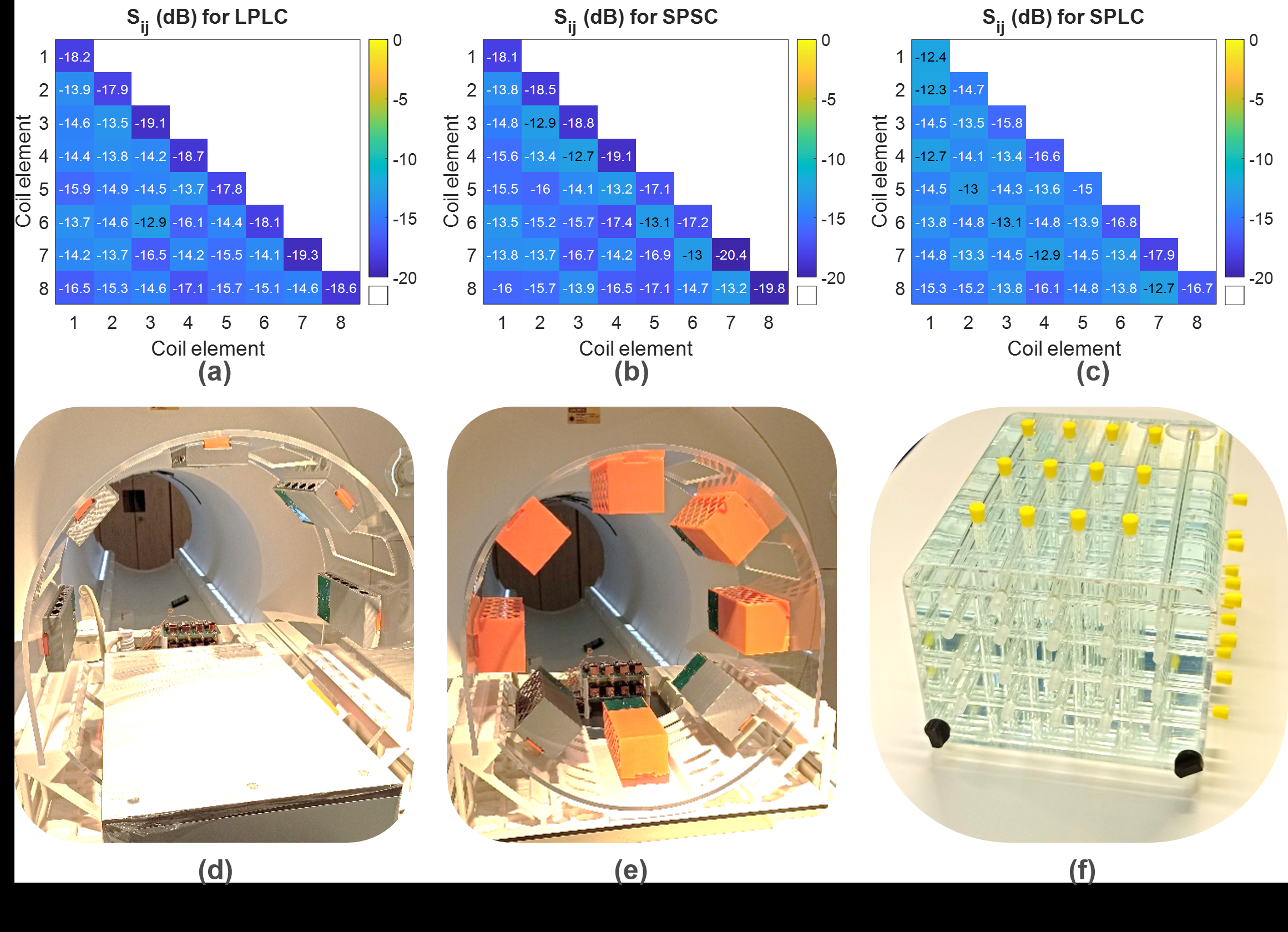
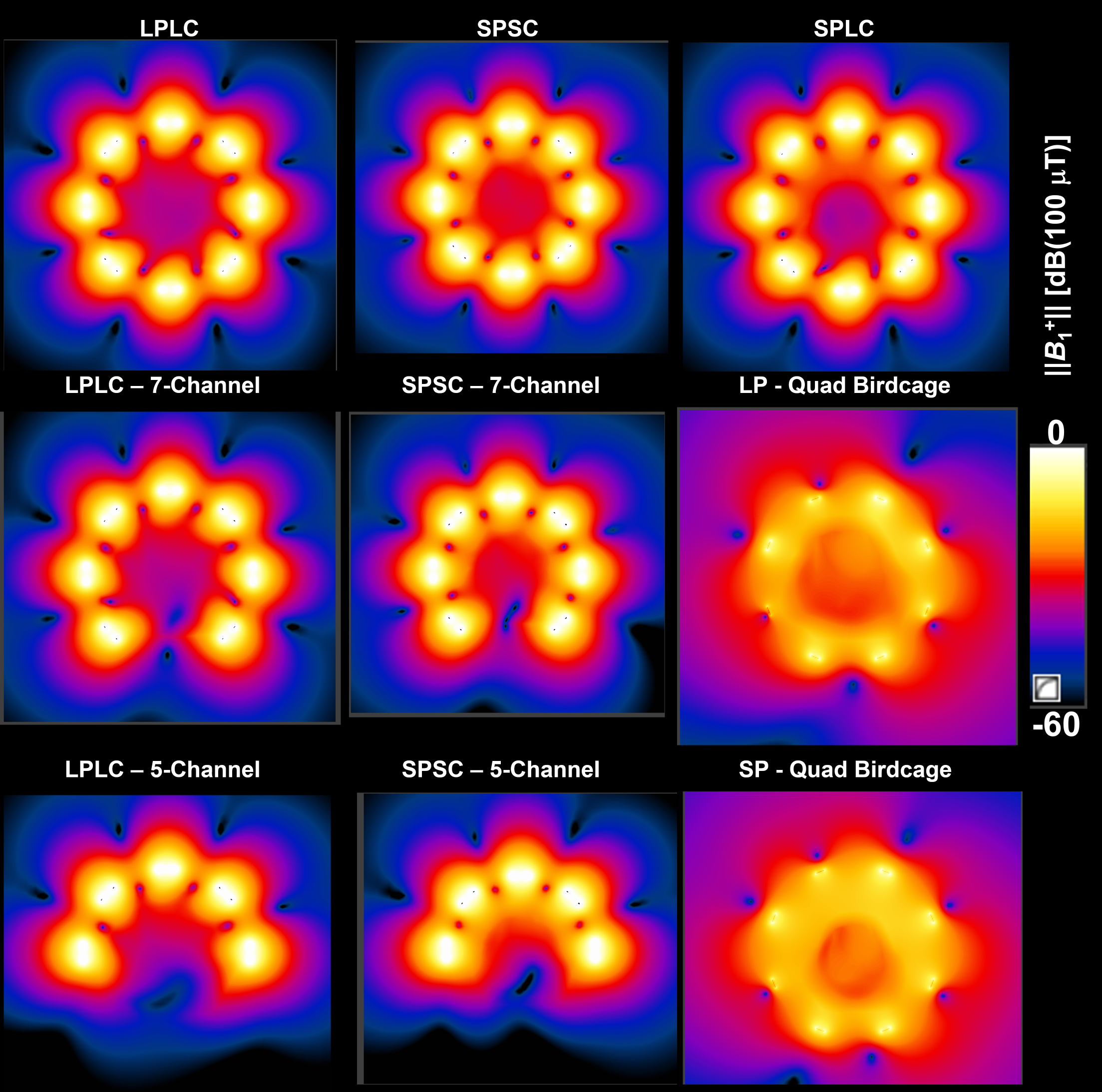
Fig. 4: ||B1+|| maps for a transverse slice across the center of the heart are shown for large-pig&large-coil with 8 (a), 7 (b), and 5 (c) channels; small-pig&small-coil with 8 (d), 7 (e), and 5 (f) channels; small-pig&large coil (g), large-pig&birdcage coil (h) and small-pig&birdcage coil (i). Birdcage coils are driven in quadrature mode. All the field maps are generated for 3kW total input power distributed equally among the Tx coil input ports.
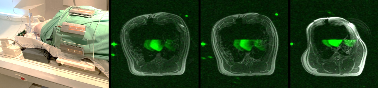
Fig. 5: Ex vivo 19F-MRI using the 8-Tx&8-Rx coil system. A photo of the cadaver measurement setup is shown on the left hand side. Three transverse slices are shown, where the 19F images are co-registered and overlaid on the 1H MPRAGE images.