1565
Balanced-force shim system for correcting field inhomogeneities due to implanted cardioverter-defibrillators (ICDs): validation in phantoms1Medicine (Cardiology), Johns Hopkins University, School of Medicine, Baltimore, MD, United States, 2Mirtech Inc., Boston, MA, United States
Synopsis
A resistive-shim system was constructed to correct the >100ppm magnetic-field inhomogeneity caused by implanted ICDs, which leads to signal loss and blurring in cardiac MRI. A plastic platform, held to the MRI stretcher, allows human-subject insertion, and holds a sensitive 720 Ampere*turns dipole-approximating shim-coil on a movable-fixture above the chest. Shim-coil is electronically decoupled from gradients and body-coil-RF. ICD field-inhomogeneity is measured with B0 mapping, and a correction field computed (shim-coil-center-location, DC-current-intensity). Shim-coil is moved to shim-coil-center-location, and a power-supply sends DC-current to the shim-coil. System was tested on phantoms overlaid with ICDs and corrected >75ppm inhomogeneity over 50x50x50mm3 FOV.
Introduction
1.4 million people in the US (2021) [1,2] have implanted ICDs. ~50% of these will require an MRI scan in their lifetime [1]. All ICDs (including MR-conditional units) contain a shielded-box w/arrythmia-detection and shock-generation units inside, which includes a ferromagnetic transformer, implanted above the rib cage in the upper-left chest wall. In many subjects, the inhomogeneous field formed by the transformer reaches the heart, with field in-homogeneities >100 PPM (>6.3KHz@1.5T) over 50x50x50mm3 ROIs observed. These cannot be completely refocused by use of “wide-bandwidth” (~1.6KHz bandwidth) [3] sequences, leading to residual-regions of signal-voids, surrounded by geometrically-distorted and motion-blurred regions, which prevent reliable diagnosis and MR-guided therapy. The scanner’s own shim coils also cannot correct these large inhomogeneities, so dedicated resistive shim coils are required, positioned either inside or outside the bore. Shim coils placed within the scanner must not displace during stretcher movement, or during time-varying gradient-currents, so force and torque must be balanced. Most shim-coil prototypes [6,7] are intended for head applications, while existing full-body systems can correct only minor (~7PPM/400Hz@1.5T) abdominal inhomogeneities [8,9]. We constructed and validated a system that corrects large ICD artifacts over the required ROI in phantoms, potentially permitting cardiac imaging of patients implanted with ICDs. Swine validation will begin soon.Methods
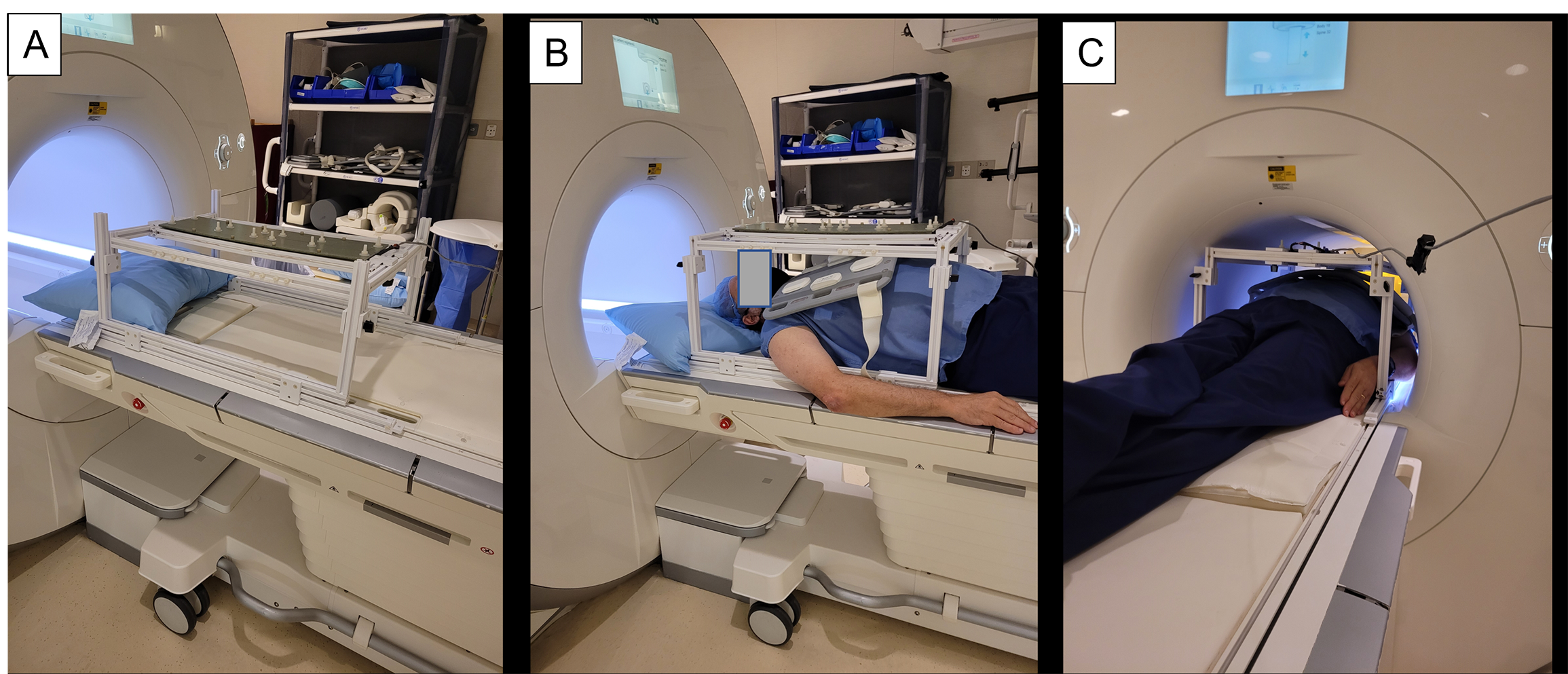
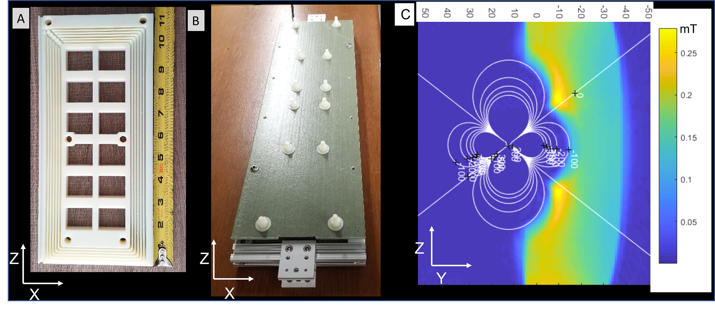
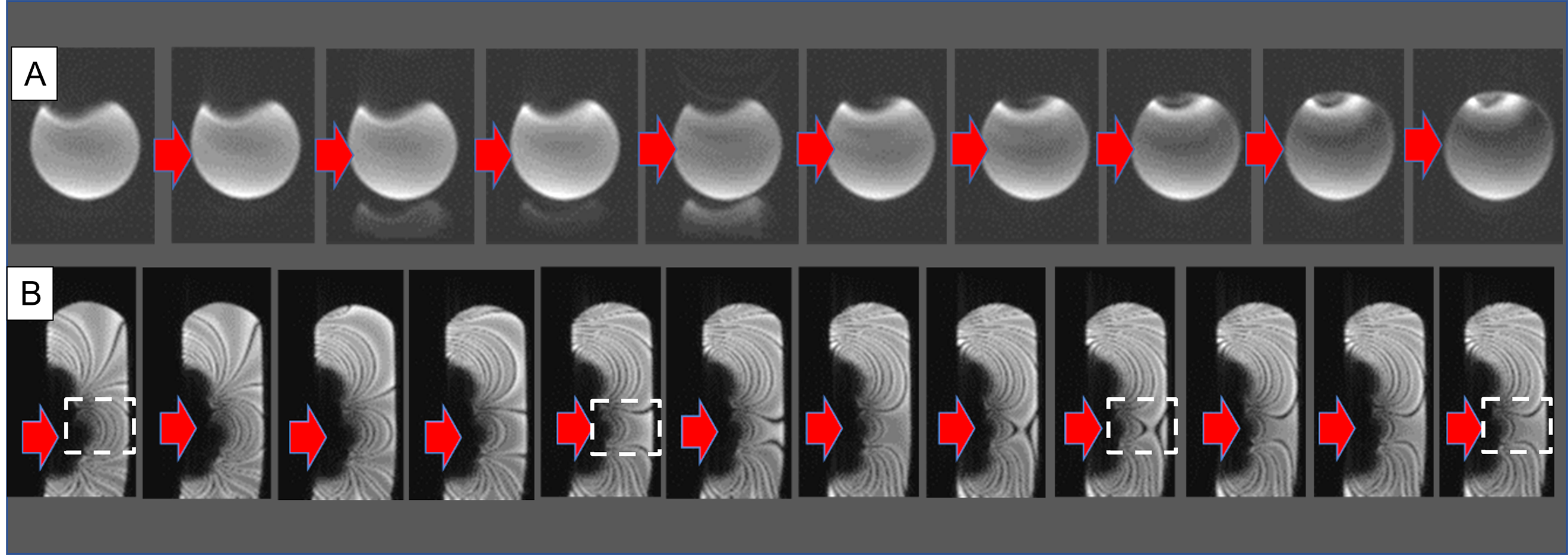
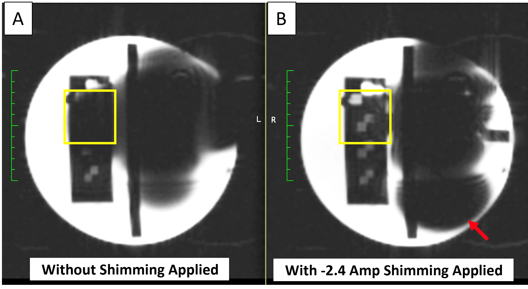
System: Shimming platform is shown on the stretcher of a Siemens 1.5T 70-cm-bore scanner with a exemplary subject inside (Figure 1). The platform is built entirely of 3D-printed plastic, and has special hooks that attach it to the Siemens MRI stretcher. The shim coil (Figure 2, Length, Width, Thickness=550mm,100mm,30mm) consists of two opposed-direction formers, each containing 36 turns of magnet wire, which creates a strong correction field (720 Ampere*turns or ~0.018mT/Ampere-current at a 150mm distance) (Figure 3) so that the correction can be realized with a power supply of <|10|Amp current. The shim-coil was tested alone (e.g. independently of the platform) inside the scanner and found not to displace, validating the balanced-(magnetic-field-based) force design. An electronic circuit [3] along the current-path between the power-supply and the shim-coil, composed of a series 10A low-pass π filter, and a series 58mH inductor, which acts as high impedance at KHz frequencies, is intended to minimize gradient-coil to shim-coil coupling during gradient-waveform transmission, which can cause otherwise cause image artifacts. The shim coil windings were also wrapped with copper tape to minimize eddy currents and thus reduce Radio-Frequency coupling to the scanner’s body coil. Since the DC-power-supply was placed outside the shielded MRI room, low-pass filters at the penetration panel reduced RF noise entering the room.Experiments: Loading and SNR of the shim-platform in a 70-cm bore 1.5T Siemens Aera scanner. We explored changes in the performance of the body-coil RF transmission energy with, versus without, the shimming-platform&shim-coil (PSC) by using the Siemens 35cm diameter sphere loading phantom and looking at the pre-scan calibration RF amplitudes. We explored changes in the SNR of TSE, GRE, and SSFP sequences with, versus without, the PSC inside the bore by imaging a cylindrical phantom (Diameter=20cm, Length=50cm). Correction of the ICD field inhomogeneity. An ICD (Boston Scientific Emblem) was placed on the superior surface of the cylindrical phantom, an 18-channel abdominal phased-array placed above, simulating a cardiac-patient’s scan, and the shimming platform mounted on top. This resulted in a highly distorted GRE image of the cylinder (Fig. 4). A B0 map was obtained using dual-echo radial Ultra-short Echo-Time (UTE) sequences (TR/TE1/TE2/Ɵ=5.76ms/0.05ms/0.3ms/5O, FOV=35cm, resolution=1.4x1.4x1.4mm3, avg=1, total Bandwidth=784KHz, magnitude/phase reconstruction). The shim-coil’s center-location (X, Y, Z) and DC-current (amplitude, phase-polarity) were then computed (Matlab 2019A, Needham, MA) by fitting the distortion over the desired R0I to a dipole field. The shim coil was moved to the location, and the computed current was supplied with a DC-power-supply. The corrected cylinder image was then observed, with further fine iterations performed by playing “real-time” 2D GRE (TR/TE/Ɵ=3.72ms/1.03ms/250, Bandwidth=1185Hz/pxl, 128x96, FOV=35x35cm2, resolution=2.6x2.6x8mm3, 0.3frames-per-seconds), or 2D balanced-SSFP (TR/TE/Ɵ=3.2ms/1.13ms/630, Bandwidth=1500Hz/pxl, 128x66, FOV=26x38cm2, resolution=3x3x10mm3 ,1.4fps) images serially while varying the DC-current, thus continuously observing changes in the cylinder’s shape or the SSFP off-resonance banding artifacts (band-to-band distance~400Hz) (Fig. 4), which permitted interactive reduction of the ICD artifact. ACR resolution- phantoms [Fig. 5] were also tested.
Results
Body Coil loading effects, GRE SNR changes and GRE/bSSFP shape distortions (including over multiple gradient-axis rotations) due to the PSC were <5%, <2%, and <0.5%, respectively.Inhomogeneity Correction With <|10|Amp current applied, we were able to first prescribe locations and currents as computed, and then iterate using serial imaging, reducing ICD artifacts from 100 to 25 PPM inhomogeneity over preselected 50x50x50mm3 FOVs [Fig. 4, 5]. Since the shim-coil’s corrective effect is limited to such an FOV volume, images of the entire heart may need to be “stitched” together by adding together images of the heart obtained with the distortion together with corrected images of the corrected region alone, similarly to multi-spectral methods used in orthopedic MRI [10, 11].
Conclusions
A balanced-force resistive-shim system to reduce large field inhomogeneities in subject’s hearts due to implanted ICDs was developed and tested in phantoms. The dipolar-approximating magnetic-field was freely moved above a “simulated abdomen” to software-determined locations and corrected >75PPM distortion over 50x50x50mm3 regions.Acknowledgements
NIH R01HL094610, R01HL157259, R01EB022011-1References
[1] Benjamin M M, Sorkness C A. Practical and ethical considerations in the management of pacemaker and implantable cardiac defibrillator devices in terminally ill patients Proc Bayl Univ Med Cent 2017;30:157–160
[2] Friedman D J, Parzynski C S, Varosy P D, Prutkin J M, Patton K K, Mithani A, Russo A M, Jeptha P. Curtis J P, Al-Khatib S M. Trends and In-Hospital Outcomes Associated with Adoption of the Subcutaneous Implantable Cardioverter Defibrillator in the United States JAMA Cardiol. 2016; 1: 900-911
[3] Shao J, Rashid S, Renella P, Nguyen K-L, Hu P. Myocardial T1 Mapping for Patients With Implanted Cardiac Devices Using Wideband Inversion Recovery Spoiled Gradient Echo Readout. Magn. Reson. Med. 2017; 77:1495–1504
[4] Rashid S, Rapacchi S, Shivkumar K, Plotnik A, Finn J P, Hu P. Modified Wideband Three-Dimensional Late Gadolinium Enhancement MRI for Patients with Implantable Cardiac Devices Magn. Reson. Med. 2017; 75: 572–584
[5] Singh A, Chen W, Alvi N, Kawaji K D, Besser S A ,Tung R D, Zou J, Lang R M, Mor-Avi V, Patel A R. Impact of Wideband Late Gadolinium Enhancement Cardiac Magnetic Resonance Imaging on Device‐Related Artifacts in Different Implantable Cardioverter‐Defibrillator Types, JMRI 2021; 54, 1257-1265
[6] Zhou J, Stockmann J P, Arango N, Witzel T, Scheffler K, Wald L L, Lin F-H. The orthogonal shim coil for 3-Tesla brain imaging. Magn. Reson. Med. 2020; 83(4): 1499–1511
[7] Winkler S A, Schmitt F, Landes H, DeBever J, Wade T, Alejski A, Rutt B K, Gradient and shim technologies for ultra high field MRI, Neuroimage 2018; 168: 59–70.
[8] Han H, Song AW, Truong TK. Integrated parallel reception, excitation, and shimming (iPRES). Magn. Reson. Med. 2013;70(1):241–247.
[9] Yang H-J, Serry F M, Hu P ,Fan Z, Shim H, Christodoulou A G, Wang N, Kwan A, Xie Y, Huang Y, Stager J, Liu W S, Azab L , Handelin R, Lu M, Yoosefian G, Wang M, Dharmakumar R, Li D, Han H. Ultra-Homogeneous B0 field for High-Field Body Magnetic Resonance Imaging with Unified Shim-RF Coils, Research Square 2021. DOI: 10.21203/rs.3.rs-445400/v1.
[10] Hargreaves BA, Worters P W, Pauly K B, Pauly J M, Koch K M, Gold G E. Metal-Induced Artifacts in MRI AJR. 2011; 197:547–555
[11] Hargreaves B A, Taviani V, Litwiller D V, Yoon L D. 2D multi-spectral imaging for fast MRI near metal, Mag. Res. Med. 2017; 79: 968-973
Figures